Street lights have become indispensable as urban lighting equipment. But at present, some street light switches are still manually controlled, and some time switches. In this way, due to the season and the weather, some street lights are turned on when the visibility is good, and the brightness cannot be changed with the change of the ambient brightness, which is a waste of electricity.
Based on the above two situations, we design a simulated smart street light controller. It can control the light on and off according to the brightness of the environment, and can automatically adjust the brightness of the light with the change of the environment.
2. Overall System Design
2.1 Design Ideas
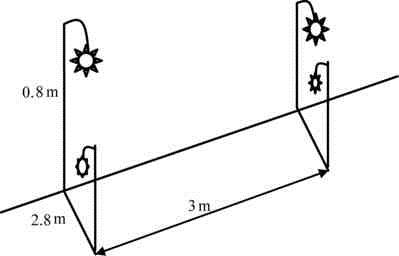
The design uses 8 incandescent lights to form two branches, and one branch has 4 street lights. Referring to the actual road conditions of each branch road, the layout of the street lights is shown in Figure 1. The street lights are hung on a bracket with a height of 0.8m, the width of the road is 2.8m, and the interval between the street lights is 3m.
The two branches are independent. Each branch is placed with 2-3 photosensitive sensors, which are used to collect optical signals and transmit the information to the single-chip microcomputer. The single-chip microcomputer decides whether to turn on the street light according to the collected light signal, and when the street light is turned on, determines the brightness of the street light according to the photosensitive signal, and realizes the control of the street light brightness by controlling the thyristor. The switch information of branch street lights is displayed on the LCD screen.
The system also comes with an automatic alarm system. Independently number the photosensitive sensors of street lights, and monitor the status of street lights and sensors in real time. Warning messages are displayed on the LCD screen.
Figure 1 Schematic diagram of the installation location of street lights
2.2 ZigBee wireless monitoring network system structure
The information transmission part of the intelligent monitoring system tries to use ZigBee technology or GPRS. Based on cost considerations, ZigBee wireless sensor network is selected.
Environmental brightness and sensor fault detection data transmission process: the remote client sends out a query request command for the working status of street lights in a certain area, and transmits it to the router through Ethernet. The router optimizes the transmission path according to the query address and selects the sink node in each corresponding ZigBee network. After the sink node receives the command, it activates all terminal nodes connected to the node to read data.
3. Terminal Node Hardware Composition
3.1 Terminal Node Control System
The controller of each branch is a ZigBee terminal node, which mainly consists of five parts: single-chip control unit, photosensitive signal acquisition unit, information display unit, fault detection unit, and brightness adjustment unit.
3.2 Function of each module in the node
The data acquisition module is mainly used to collect changes in ambient brightness and fault detection. The photoresistor realizes the change of its brightness and darkness, and generates different voltages to send to the single-chip processor, which is converted into a digital signal by the internal A/D converter of the single-chip microcomputer. The processor performs corresponding processing according to the detected signal, so as to change the switch state of the light due to environmental changes.
The microprocessor unit is mainly responsible for receiving and processing the information sent by the data acquisition module. The single-chip microcomputer performs arithmetic processing according to these information, and adjusts the thyristor through the output interface circuit to realize the intelligent control of the switching time of the light and the brightness of the light.
The photoresistor detects the fault information and also gives an alarm signal on the LCD screen after being processed by the single-chip microcomputer.
The wireless transceiver chip is mainly used to exchange data with other nodes in the network to form a mesh network. The brightness adjustment part of the street light is adjusted by thyristor.
4. Software Design
The main program starts out in a pending state. When the start button is pressed, the program starts, and when the close button is pressed, the program closes. Of course, the actual situation basically does not need to be closed.
During the normal operation of the program, the A/D acquisition part of the single-chip microcomputer collects the voltage signal transmitted by the photosensitive sensor, performs signal filtering processing after receiving the signal, and judges whether the sensor is faulty according to the value of the voltage signal.
With the lights off, it is determined whether the lights should be turned on. When the light is turned on, within a period of time, according to the voltage value, it is judged whether the light is faulty and whether the street light should be turned off. Whether the light is turned on or not, the switch information of the light, the status of the sensor, and the status of the light should be displayed in real time.
5. Test
This paper tests a network consisting of a total of four nodes. First, the coordinator program is written to one node, and the router program is written to the other three nodes. Then connect one end of the RS232 line to the serial port of the computer, and the other end to the coordinator node. Display the output content through the serial port debugging assistant.
The serial port adopts the following configuration: bit rate 19200, 8 data bits, 1 stop bit, no parity and data flow control bits. Turn on the power of each node, and the power indicator lights up. After about 1 to 2 seconds, the LED flashes, indicating that the node has started to report monitoring data.
The main functions implemented are as follows:
Street light switch time control,
The control of street light brightness,
Bad sensor and bad street light warning prompt,
The function of independent control of each branch.
6. Conclusion
Many of the current municipal automatic control parts do not have the function of changing the state of the light with the change of the environment, but only rely on artificially setting the time of switching the light, and the brightness of the light is not adjustable. This design realizes the automatic control of the state of the street light, and the brightness and time can be adjusted in real time according to the changes of the environment.