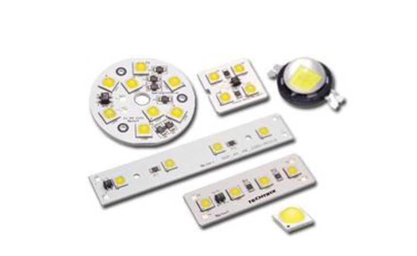
Why Can’t we Use White LEDs for Overvoltage or Overcurrent?
Generally, the most commonly used 5mm x 5mm white light LED, its normal working voltage is mostly in the range of 3.0-3.5V, and the normal working current is 20mA. However, many people mistakenly think that using white LEDs for overvoltage or overcurrent will be brighter. The actual test result is that the luminous flux increases very sharply after 15mA. After 20mA, there is almost no improvement. It increases to 30mA, which is only 5% more than 20mA. There is obvious fever. There is also a life test: 20mA work for a month, the attenuation is only 5%, and now there is 95% luminous flux, and 30mA work until 19 days, the luminous flux is only 50%. It can be considered that a white LED that can work for 100,000 hours under normal conditions will have a lifespan of only 600 hours when used under high current.
In general instructions, LEDs can be used for more than 50,000 hours. Some manufacturers claim that their LEDs can operate for about 100,000 hours, but this does not guarantee that LED products can be used for such a long time. Wrong operations and procedures can easily “destroy” LEDs. LEDs will gradually degrade over time. Studies have shown that high-quality LEDs can maintain the initial brightness of 60% after 50,000 hours of continuous operation. %the above. In order to extend the life of the LED, it is necessary to reduce or completely dissipate the heat generated by the LED chip. Thermal energy is the main reason why LEDs stop functioning.
Why is the color of the light emitted by the white LED always bluish or yellow?
This is due to the fact that the white LED is originally covered with the conversion material phosphor on the blue-emitting 1nGaN base material, which emits yellow light when excited by the blue light. The result is a mixture of blue and yellow light, which is white light to the naked eye. Looking at the emission spectrum of a white LED, you know that it has two peaks, so there is no LED that truly emits white light. Such devices are difficult to manufacture, because LEDs are characterized by only emitting single-color light of one wavelength, while true white light requires multi-color spectral synthesis. Due to the process, including imported LEDs of more than ten yuan, there is also this problem. There is a color cast at the edge of the light spot, which is just a few. White light-emitting diodes have yellowish to purplish white light. The color temperature of common white light emitting diodes is usually in the range of 4500K to 7500K.
Is it better to use parallel connection or series connection for LEDs?
The LED adopts parallel or series connection method, which should mainly be determined according to the form and requirements of the power box circuit. Parallel or series connection methods have their advantages and disadvantages. The parallel connection method only needs to apply a lower voltage at both ends of each LED, but needs to use a ballast resistor or current source to ensure that the brightness of each LED is consistent. If the current flowing through each LED is different, their brightness is also different, resulting in uneven brightness of the entire light source. However, using ballast resistors or current sources to ensure consistent LED brightness will shorten the life of the power supply.
When the LED adopts the parallel connection method, since the total current of the circuit is the sum of the current of each LED, the power supply is required to be able to supply a large enough current. In essence, the series connection method can ensure the consistency of the current flowing through each LED, but the power supply voltage is required to be high. In addition, in a circuit with series connection, when one of the LEDs is disconnected, the entire string of LEDs will not light up; but when one of the LEDs is short-circuited, the other LEDs can still light up. Using the parallel connection method, when one of the LEDs is disconnected, the other LEDs can still light up; but when one of the LEDs is short-circuited, the power supply of the entire circuit will be short-circuited, so that not only the other LEDs cannot work normally, but also It may also damage the power supply.
Therefore, the circuit with series connection method is more advantageous in comparison. In practical applications, LED arrays formed in series and parallel are often used, which can overcome or reduce the above-mentioned single LED open circuit or short circuit causing the entire string of LEDs to not light up or the impact on the entire circuit and power supply. The so-called series-parallel connection is to use a small number of LEDs in series and then series ballast resistors to form a branch, and then connect several branches in parallel to form a “branch group”. In addition, the serial-parallel-series form can also be used, that is, on the basis of the formed “branch group”, a number of “branch groups” are connected in series to form the entire lamp circuit.
This connection method not only reduces the failure of one LED In addition, the ballast resistance is reduced to zero, and several high-power resistors are turned into dozens of low-power resistors. From centralized installation to decentralized installation, this is not only conducive to the resistance heat dissipation, but also can make the design of the lamp more compact.
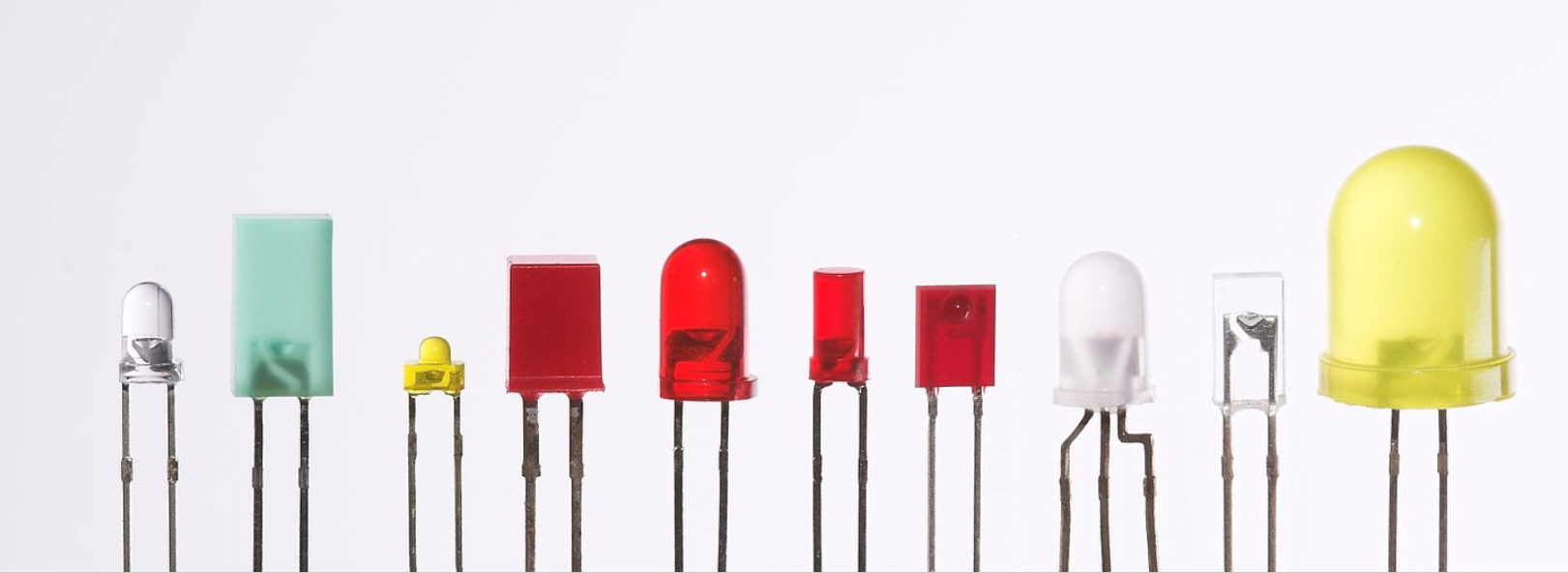
Can LED light-emitting diodes of other colors be used instead of white light-emitting diodes?
Absolutely okay. However, it must be noted that the normal working voltages of LEDs of various colors are different and the difference is large. For example, the normal working voltage of red and yellow LEDs is only about 2V, while the normal working voltage of blue and green LEDs is closer to that of white LEDs. Both are around 3V. Therefore, according to the working voltage of various tubes, the number of tubes connected in series or in parallel must be changed accordingly, or the resistance of the current limiting resistor connected in series must be changed, otherwise the LED may exceed the normal working current and shorten Its service life may even burn down the LED.
When using red or yellow LEDs, the number of LEDs connected in series should be increased, or the current limiting resistor in series should be increased; when using blue or green LEDs, generally only adjust the resistance of the current limiting resistor.
What is the difference between concentrating LED and astigmatic LED? How to choose?
The luminous intensity value of the condensing LED is very high, because its light is aggregated by itself, so its luminous angle is generally small, the light irradiation range is small, and the light emitted is like the beam of a flashlight. The brightness of the light spot is high, but the periphery of the light spot is not too high. The astigmatic LED has a low luminous intensity value, and its light-emitting angle can reach more than 120 degrees. Therefore, its illumination range is large and the light emitted is uniform, just like the light emitted by ordinary lighting. The standard brightness values are generally low, but in fact the total luminous flux (total light) emitted by them is generally higher than that of concentrating LEDs.
Concentrating LEDs are most suitable for occasions that require high brightness but a small range of illumination, such as spotlights, downlights, flashlights, etc., while astigmatic LEDs are more suitable for general room lighting and those that require soft and uniform light. Occasion, therefore, should be selected according to the specific situation to achieve the best lighting effect.
What is the reason why the light does not turn on when the circuit is installed and energized? How to check?
This requires specific analysis based on specific circuits. But most of the reasons are that the LED was not tested before the installation or the positive and negative polarity of the LED was accidentally connected incorrectly during the installation and welding process, or it may be caused by the failure of the welding (the virtual welding is the appearance of welding. However, the actual soldering is not strong). Welding is the main reason for this failure, especially for novices who lack soldering experience. This problem is most likely to occur. The second is that the power of the electric soldering iron is too high or the soldering time is too long and the pipe is burnt. , It is also possible that the electric soldering iron leakage caused the LED to break down and short-circuit.
There is also a part of the drive circuit that is connected incorrectly or not soldered well, and some circuits may also have the component values that should be adjusted have not been adjusted properly. When the circuit is installed, it should be checked carefully before powering on. If the light does not turn on when the power is on, turn off the power immediately, and then check again. Do not tap the circuit board with power to try to find the fault, especially the circuit with 220V power supply. in this way. If it is a circuit with a filter capacitor, you should first use a screwdriver or a wire to short-circuit the two feet of the filter capacitor and then perform the inspection. This step is very important.
Because the filter capacitor has a high voltage that is more than 1.4 times the power supply voltage (for example, it can be as high as 310V when the power supply is 220V), so as to prevent the high voltage remaining on the capacitor from hurting the human body or destroying the LED when the circuit is turned on. Check the LEDs that have been installed and soldered on the circuit board. You should first recognize the negative mark of the notch on the LED tube body, check whether the polarity of each LED is incorrectly connected, and then use two batteries in series to lead out the positive and negative power supplies to touch each one.
For the two legs of the LED, you must pay attention to the polarity of the battery power supply to be consistent with the polarity of the LED to check whether each LED can be lit. For the inspection of the drive circuit, you should carefully check whether the circuit is connected incorrectly according to the circuit diagram. Pay special attention to the rectifier bridge (the long leg is the positive output, the opposite corner is the negative output, and the other two pins are the AC input) or the rectifier diode and Zener diode Whether the polarity is correct (the end printed with a black line or a white line is the negative electrode), and check whether the three electrodes of the transistor or the voltage stabilizer integrated circuit are connected incorrectly.