1. Design Analysis of Intelligent Solar Street Light System
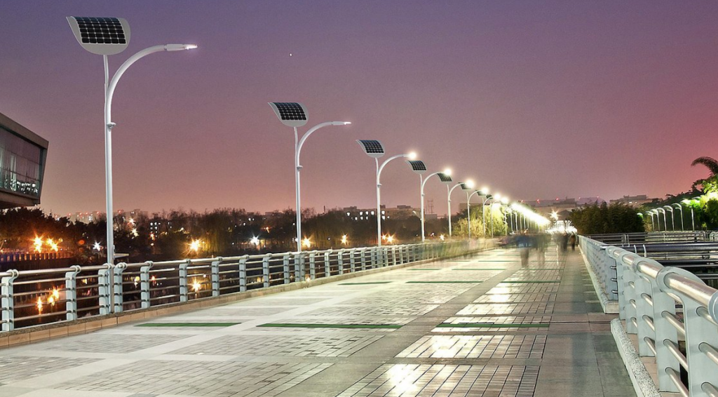
At present, with the acceleration of urbanization construction and the acceleration of urban infrastructure construction, the market demand for lighting products in cities is gradually expanding. Under the background of energy shortage, traditional lighting equipment consumes a lot of energy, and there is a huge waste of energy, which also affects the urban ecological environment. This is obviously not in line with the development direction of energy utilization, and also greatly limits the utilization efficiency of lighting equipment. The emergence of solar street lights has effectively made up for the above shortcomings.
1.1 Overview of system functions
(1) Light intensity tracking
For the solar panel to face the direction of the strongest light, the system must find the direction of the strongest light source in its environment. Use a microcontroller to read the values of 32 photosensitive sensors on the sensor array, and use a correction algorithm to correct it, find the direction with the strongest light, and determine the direction the solar panel needs to face.
(2) Charging and charging control
Solar cells can only generate electricity when there is sunlight. Collect this energy and use it when you need it, that is, street lighting at night. Solar panels can also generate a certain amount of current and voltage in cloudy days and other non-direct sunlight environments, and sometimes they can meet the charging bar conditions, and sometimes they can’t.
If the conditions are met without charging, it will lead to low charging efficiency and waste solar energy resources. On the contrary, if the charging circuit is turned on when the conditions are not met, it will cause the current to flow backwards, and the solar panel will become an electrical device, causing the solar panel to heat up or burn out. Therefore, the system must monitor the voltage value generated by the solar panel and the reading of the photosensitive sensor, and only open the circuit to charge when the conditions are met.
(3) Human-computer interaction
A simple interactive system is conducive to the judgment and maintenance of faults. System information such as light intensity readings, solar panel voltages, and system operating status are displayed on a simple LCD screen, allowing installers and maintenance personnel to quickly implement and troubleshoot installations.
1.2 Hardware system design
(1) Design of light sensing system
In an outdoor environment, the light available from a solar panel is roughly a hemisphere in all directions. Therefore, forming a hemispherical sensor array can monitor the light intensity of the effective light in the whole environment.
Divide a hemispherical object into multiple areas by latitude and longitude, and each area corresponds to the incident area of a light. A photosensitive sensor is installed in the center of each area, and the light intensity of the corresponding area is monitored, and we can know which area has the highest light intensity. If higher accuracy is required, a finer division can be made and more sensors can be installed. For smart street lights, 32 sensors have fully met their accuracy requirements.
(2) Solar panel follow-up system design
Solar panels need to be flexibly and precisely aligned where the light is strongest. In addition to the need for horizontal rotation, it is also necessary to be able to adjust and control the vertical angle of elevation. Use multiple servos to form a gimbal that can freely control the direction of the solar panel within a range of 180° in the vertical direction and 360° in the horizontal direction.
(3) Design of charging system
The voltage and current generated by the solar panel may not always meet the conditions required for charging, and must be judged by the single-chip microcomputer. When the conditions are met, charging is performed. In order to make the charging efficiency better and make the charging continue and stably, a voltage regulator module is used to make the acceptable voltage of the solar panel in a wider range. When the light intensity is small on cloudy days, the voltage is boosted, and when the light is stronger, the voltage is correspondingly reduced.
2. Application of Electronic Ballast Energy-saving Technology
In lighting engineering, ballast is an indispensable and important member. Its development has also attracted more and more people’s attention. For example, in road lighting, cost-effective lights and light sources are mainly used for new roads, and new energy-saving products are used for old roads. Therefore, the use of energy-saving ballasts is a good energy-saving strategy for street lights.
Advantages of electronic ballasts
Compared with traditional magnetic ballasts, high-pressure sodium light electronic ballasts have superior energy-saving performance. Taking 250W as an example, the first is low power consumption, strong illuminance, and constant power output. The power consumption of the electronic ballast itself is only 12W, while the power consumption of the inductive ballast itself is about 40W. In the case of the same illuminance, the input power of the electronic ballast is 283.5W, while the traditional inductive ballast is 315W, and the difference saves 30W. In addition, the energy saving effect of using electronic ballasts is more obvious after the voltage is increased. Because the electronic ballast has a constant output power, the voltage is between 170V and 260V, and the output power is always 250W, while the inductive ballast basically works at 320W for about 6h in the second half of the night.
Power automatic adjustment function
The electronic ballast also has the function of automatic power adjustment. For street lights, when there is no one on the road in the middle of the night, the electronic ballast can reduce the power of the sodium light to 150W, thereby effectively reducing the power consumption.
The power factor of the electronic ballast is 0.98, while the inductive ballast is about 0.4 without the compensation capacitor, and only 0.7 to 0.8 with the compensation capacitor. The working power of the sodium light is 250W under the control of the electronic ballast, while the power under the control of the inductive ballast is about 320W. The apparent power is: 255VA and 400VA, the difference is 145VA, that is, the flow required for a single sodium light to be changed to an electronic ballast is 145VA more than that of an inductive ballast. In this way, in the initial stage of construction, the capacity of the transformer and the wire diameter of the cable can be reduced, thereby greatly saving the investment cost. When expanding, it is unnecessary to add transformers.


