4. Research on the Heat Dissipation and Design of LED Lights
4.2 Establish a mathematical model of the component heat sink
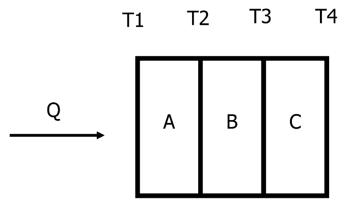
Schematic diagram of heat conduction of the heat dissipation substrate
4.3 Finned radiator design
The parameters that affect the performance of the fin radiator are: the length, width, and thickness of the base, and the height, thickness and spacing of the fins. For multi-factor parameter design choices, orthogonal experiments can be used for experiments, which can reduce the number of experiments.
Calculate the result according to the obtained orthogonal table, and then perform the range analysis. Studies have shown that both the heat dissipation area and the fin structure of the radiator will affect the junction temperature.
The thickness of the rib base is also a factor that has an important influence on heat dissipation. Among them, the influence law of the rib base on the junction temperature is: when the thickness of the rib base changes within a certain range, the junction temperature will increase as the thickness of the rib base decreases. But when the thickness is higher than this range, the junction temperature will increase as the thickness of the rib base increases. The reason is that within a certain range, the increase in the thickness of the rib base is conducive to heat transfer in the direction of the ribs. If the thickness of the rib base exceeds this range, the longitudinal heat transfer resistance will increase as the thickness increases. This will adversely affect heat dissipation and cause the chip temperature to rise.
In summary, when designing the thickness of the rib base of the LED lamp, you cannot only rely on increasing the thickness of the rib base to enhance the heat dissipation performance, and you should also consider the actual need to design the rib base.
4.4 Design optimization of heat dissipation structure of LED lamps
Optimize the heat dissipation structure
The thermal field analysis of LED lamps has been carried out above. In practical applications, thermal field analysis can help optimize the design of the heat dissipation structure of the lamp. For the factors that affect the performance of the radiator, the previous analysis was also carried out. This section continues to discuss the optimization scheme.
The use of a multi-chip, low-power chip layout is beneficial to the reduction of the junction temperature of the chip in the LED lamp, and is also an important means to effectively reduce the coupling. However, from the perspective of optical layout, when optimizing multi-chip LED components, the modification of the chip array is generally not considered as the primary consideration, but the optimization of the component size is the primary consideration for improving the heat dissipation structure.
When the power of each chip is 1W, the more the number of chips and the greater the power, the more heat will be generated. What follows is that the thermocouple phenomenon is more serious, and the junction temperature of the chip will also develop in a higher direction. But when the total power is constant, as the number of chips increases, the power of a single chip changes in a smaller direction, and the temperature distribution also develops in a uniform direction.
As the number of chips increases, the power of the LED array also increases, and the corresponding increase in the junction temperature of the chips will not be conducive to heat dissipation. In this case, if the number of chips around a single chip increases, the thermocouple phenomenon of the chip will increase, and the junction temperature will rise accordingly. Such a vicious circle will not be conducive to the heat dissipation of the chip.
The effect of the number of chips on the junction temperature
In summary, when the total power is determined to be constant, the power of a single chip will decrease as the number of chips increases. The temperature will also develop in a more uniform direction. Relatively speaking, the junction temperature will also become smaller. When the number of chips is small, the power of a single chip is higher, which is not conducive to heat dissipation. Therefore, in terms of chip array layout, an optimized direction is to change to a multi-chip low-power layout.
Through the analysis of the multi-chip thermal field in the LED lamp, it is found that when the heat dissipation area is constant, increasing the length in the Z span direction is very beneficial for the enhancement of the heat dissipation function of the chip and the weakening of the thermal coupling between the chips. Therefore, when optimizing a multi-chip LED array with a constant total power, the wing direction layout is used as the principle, and the array arrangement is performed, and then the finite element analysis of the thermal field distribution can realize the optimized design of the heat sink. In this way, the heat dissipation effect of the component can be better.
Finite element analysis method
It is a kind of finite element analysis method to replace the original complicated problem with simple problem. Using this analysis method, the solution domain is discretized, and many small subdomains are obtained. Then solve each subdomain, and then derive the condition that satisfies the entire domain, and then get the solution of the complex problem.
Different from other boundary value solving problems, the finite element analysis method is limited to the approximate solution of small subdomains. It is relatively simple to use the finite element method to solve the geometric shapes formed by the discrete regions, such as forming triangles or arbitrary quadrilaterals in two-dimensional analysis. This is the advantage of finite element analysis: the boundary conditions of the requested area are relatively simple, and there is no need to calculate the boundary conditions.
For the power type lamps in the LED, it is not a single working state. From the chip power on and start to work, to heat generation and gradual accumulation, this process is transient. As time changes, the junction temperature of the chip continues to rise, so the thermal field is not stable in this case. The heat balance equation can be obtained according to the law of conservation of energy under transient conditions, as shown in equation (3). In the formula, K represents a conduction matrix containing four different indicators: thermal conductivity, convection coefficient, emissivity and shape coefficient.
CT+KT=Q
(3)
The thermal stability of the LED chip
In the case of the model geometric parameters, the performance parameters can be used in the selection of the finite element method, and then the boundary conditions are added to it, and the formula is deduced to obtain K, T and Q. The final heat balance equation can be obtained. In the end, solving the equations can get the evaluated value, and the control equation of ANSYS in steady state can be expressed by equation (4).
After the chip has been working for a period of time, the temperature of the chip will continue to rise until it enters the steady state stage. At this time, the boundary conditions have reached a fixed value. When analyzing the thermal stability of the system, the system must be in a thermally stable state. At this time, if the heat generated by the system itself is exactly equal to the difference between the inflow and outflow of the system, then this state will be referred to as the static heat flow rate of the system is zero. A system in this state can also be said to be in a thermally stable state. At this time, thermal analysis is performed, and the temperature of each node under steady-state conditions will not change due to changes in time. That is to say, the node temperature has nothing to do with the change of rain time under the thermal steady state. Therefore, in the thermal steady-state analysis, the energy balance equation can be expressed in matrix form, as shown in equation (5).
{K}{T}={Q}
(5)
5. Conclusion
LED lamps continue to progress and develop, and gradually become popular. The distributed design is very effective in improving the heat dissipation effect, and promotes the extension of the life of the LED lamps and the enhancement of the performance. Starting from the analysis of thermal coupling, analyze the factors that affect heat dissipation. An optimization plan is proposed for the design of the heat dissipation structure, and the design of the thermal field distribution is more reasonable.
The main conclusions are: based on the thermal research of LED lamps, the thermal characteristics of the distributed structure are studied, which provides the basis for the establishment of the model. The thermal field coupling is studied, and the mathematical model of the component heat sink is established. The considerations for the design of the finned radiator are analyzed. The finite element analysis method is used to obtain the steady-state control equation, which provides a basis for ANSYS and realizes the design optimization. The research results have guiding significance for improving the heat dissipation performance of LED lamps, and provide ideas and methods for the design of distributed LED lamps, which are of great significance.


