An LED light contains from one to a dozen or more LED chips, which are usually connected in series. The brightness of each chip is determined by the amount of current passing through it.
Due to the series connection, each LED chip in the bulb will automatically pass the same current, but the voltage on each chip is different. The forward voltage drop of an LED is typically 3.4V, but can vary from 2.8V to 4.2V. We can categorize LEDs to limit voltage swings, but this adds cost. And the forward voltage drop still varies with temperature and usage time.
To provide consistent light output, LED lamps must be driven by a highly regulated, high-efficiency constant-current power supply. As an alternative to incandescent lamps, the LED lamp power supply must be integrated into the lamp housing.
A typical integrated LED lamp includes a driver circuit, an LED cluster, and a housing that provides mechanical protection and heat dissipation for both the driver and the LED chip.
The requirements for LED drivers are very strict. It must be energy efficient, meet stringent EMI and power factor specifications, and safely withstand a variety of fault conditions.
One of the most difficult requirements was dimming. Poor performance is likely due to a mismatch between the characteristics of LED lamps and dimmer controllers designed for incandescent lamps.
Problems can manifest as slow startup, flickering, uneven lighting, or flickering when adjusting the brightness. In addition, there were problems with inconsistent performance of the individual units and audible noise from the LED lights. These negative conditions are often caused by a combination of factors such as false triggering or premature shutdown of the controller and improper LED current control.
Dimming Controller
way to control
Lighting controllers work in line dimming or PWM dimming. The simplest form of line dimming is the leading edge thyristor controller. This is by far the most common way to control lighting, but unfortunately, dimming LED lights with thyristor controllers creates a lot of problems. More advanced line dimmers are electronic leading or trailing edge dimmers. PWM dimmers are used in professional lighting systems.
SCR dimming
When using leading edge thyristor dimmers, dimming control is achieved by changing the phase angle of each half-cycle of the thyristor’s conduction. The input power of the bulb has a certain functional relationship with the phase angle of the dimming signal, and the phase angle varies from approximately 0° to 180°.
One of the important parameters of the thyristor is the holding current (IH). This is the minimum load the thyristor must sustain to stay on without using gate drive. In order to maintain the stable operation of the thyristor, the current cannot be zero, and the typical value of IH is between 8mA and 40mA.
Therefore, phase angle dimmers for incandescent lamps usually have a specified minimum load, typically 40W at 230V AC rated voltage. This is to ensure that the current through the internal thyristor is always above the specified holding current threshold.
Problems in LED light dimming
Since the power consumption of LED lighting is very low, maintenance current will be an issue.
Another potential problem is inrush current. When the thyristor is turned on, high inrush current flows into the LED light. The worst case is when the phase angle reaches 90°, at which point the AC input voltage peaks. For incandescent lamps, inrush current is not a problem. But in LED lamps, the driver’s input stage impedance and line capacitance can cause oscillations. When oscillation occurs, the thyristor current will immediately drop below the holding current, causing the thyristor to stop conducting.
To solve these problems, it is necessary to modify the specifications and design of the LED driver.
Non-isolated Dimmable LED Driver
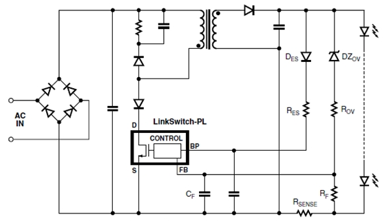
Figure 1 shows a basic application circuit diagram of a non-isolated dimmable LED driver that can be used to replace incandescent LED lamps. The function of the driver is described below in order to clarify the problems that the driver will have when it becomes the load of the thyristor dimmer.
Figure 1: Application circuit diagram of a non-isolated LED driver.
The controller integrates high-voltage power MOSFET switches and power controller on a single IC. The device provides single-stage power factor correction (PFC) and LED current control. This circuit can be used as a discontinuous mode, variable frequency, variable on-time flyback converter.
The rectified AC power input is switched by an integrated 725V power MOSFET through a high frequency transformer. The voltage developed on the secondary winding is rectified and smoothed before it becomes the LED load.
The LED load current also flows through the sense resistor RSENSE. The voltage developed on RSENSE (typically 290mV) appears at the FEEDBACK (FB) pin via RF, providing accurate constant current feedback control. DES and RES power the LinkSwitch-PL, and DZOV and ROV provide overvoltage protection in the event of an open LED.
The transition of lighting from old technology to new technology is still years away. During this time, the challenge for LED lamp designers is to ensure that the new designs are compatible and work reliably with existing controllers and wiring architectures originally developed for incandescent lighting.
Inrush Current
As shown in Figure 1, the driver constitutes a high-impedance, large-capacitive load to the thyristor controller. In addition, there will be an input EMI filter circuit composed of capacitors and inductors. At each half cycle, inrush current is generated, causing oscillations (as described above).
For trouble-free dimming operation, the driver must be able to limit oscillation and prevent the thyristor current from falling below the holding current value. Figure 2 shows the complete circuit diagram of a driver with this capability.
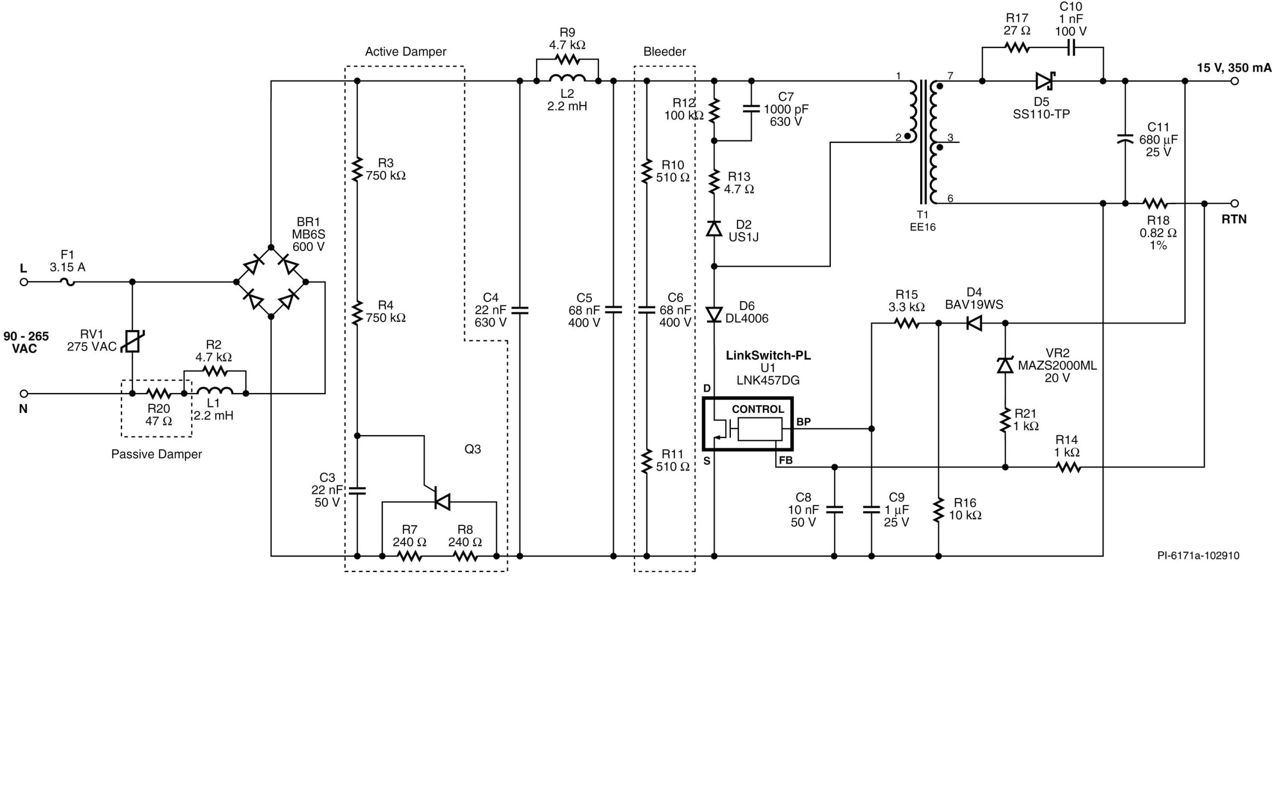
Figure 2: Circuit diagram of a 5W, 15V SCR dimming LED driver for A19 incandescent replacement lamps
Function of thyristor dimmer
The circuit in Figure 2 provides a single constant current output of 350mA and an LED string voltage of 15V. Using a standard AC power thyristor dimmer reduces output current by 1% (3mA) without causing instability or flickering of the LED load. The driver is compatible with both low-cost thyristor dimmers and more complex electronic leading and trailing edge dimmers.
The driver’s functionality adds input EMI filtering and three components unique to thyristor dimming: a passive attenuation circuit, an active attenuation circuit, and a bleeder circuit.
Input EMI filtering ensures compliance with IEC ring wave and EN55015 conducted EMI regulations. However, the key point is that the LinkSwitch-PL controller integrates a built-in frequency jitter feature. This feature spreads the switching frequency and reduces EMI peaking, allowing the size of the EMI filter circuit to be much smaller than normal. This helps to greatly reduce the inductive load on the SCR, thereby reducing the possibility of oscillation.
Passive attenuation circuit
Resistor R20 constitutes a passive attenuation circuit. The active attenuation circuit connects series resistors (R7 and R8) through the input rectifiers during each AC half cycle and bypasses the resistors through a parallel thyristor (Q3) during the remaining AC cycles. Resistors R3, R4 and C3 determine the delay time before Q3 turns on, then shorts the decay resistors R7 and R8. The passive damping circuit and the active damping circuit work together to limit the peak inrush current when the thyristor is turned on each half cycle.
Resistors R10, R11 and C6 form a bleeder circuit to ensure that the initial input current amount can meet the holding current requirement of the thyristor, especially when the conduction angle is small. For non-dimming applications, passive attenuation circuits, active attenuation circuits, and bleeder circuits can be omitted.
Isolated LED Driver
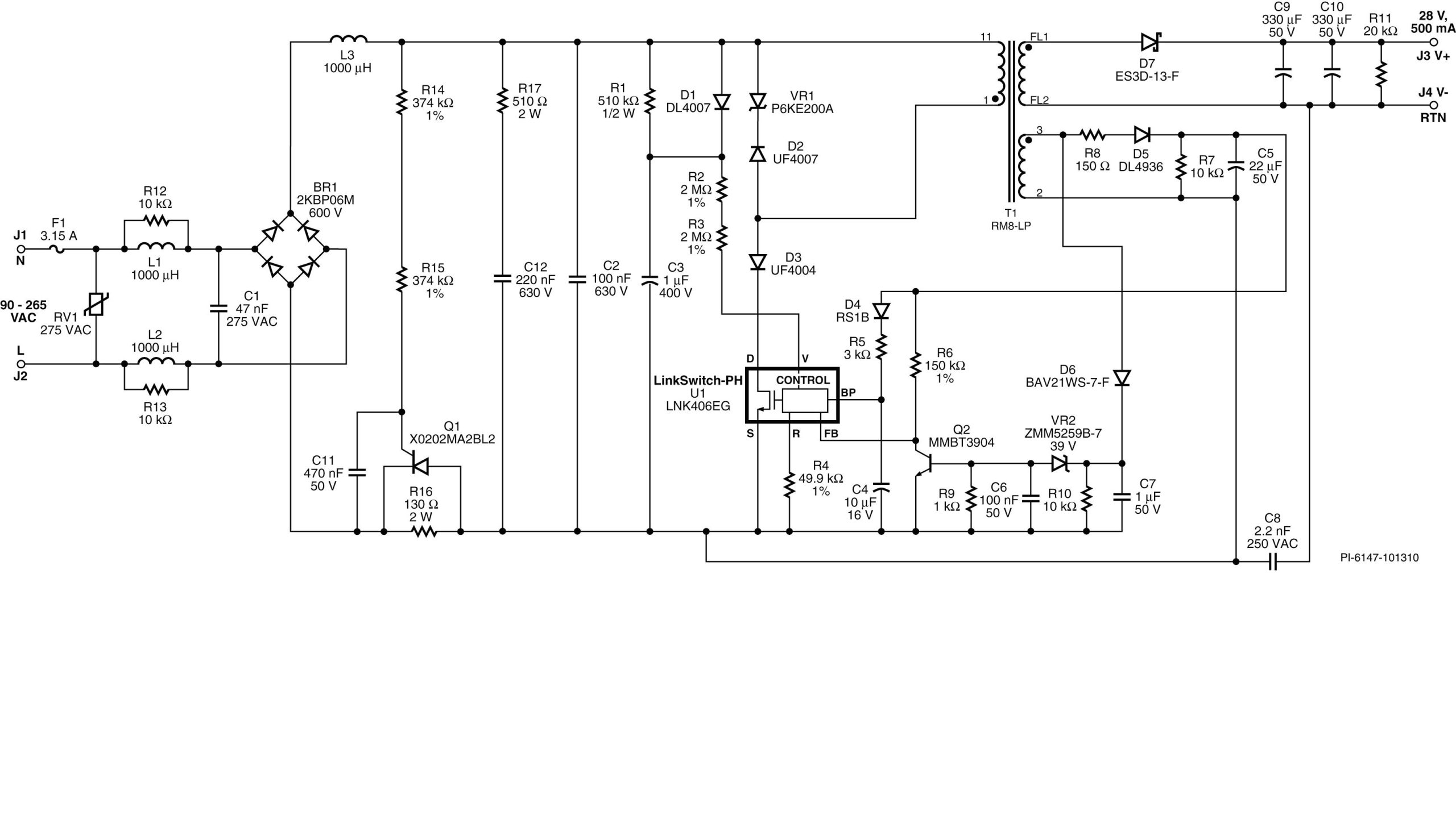
The driver in Figure 2 is optimized for low power, electrically non-isolated integrated LED replacement lamps. PI has introduced the LinkSwitch-PH controller for higher power LED lighting systems that require electrical isolation. Figure 3 shows the circuit diagram of an isolated LED driver using LinkSwitch-PH.
Figure 3: Circuit diagram of a 14W SCR dimming high power factor LED driver.
Working Mechanism
The circuit is capable of delivering 0.5A drive current to a nominal LED string voltage of 28V over an input voltage range of 90VAC to 265VAC. Features include ultra-wide dimming range, flicker-free operation (even with low-cost AC input thyristor dimmers), and fast and smooth turn-on.
The topology it uses is an isolated flyback operating in continuous conduction mode. Output current regulation is completely sensed from the primary side, so no secondary feedback components are required. A single-stage internal controller adjusts the duty cycle of the high-voltage power MOSFETs to keep the input current at a sinusoidal alternating current, ensuring high power factor and low harmonic currents.
Function
The function of this circuit is generally similar to the circuit in Figure 2, the most obvious difference being that the circuit uses electrical isolation and does not use a sense resistor in series with the load.
Feedback control is provided through the bias winding on the transformer. The feedback control has two functions: powering the LinkSwitch-PH via the bypass (BP) input and providing current feedback via the feedback (FB) input.
Another important input provided by the LinkSwitch-PH is the voltage monitor (V). This pin is connected to the external input voltage peak detector interface, which consists of D1, C3, R1, R2, and R3. Impressed current is used to control the stop logic for input undervoltage (UV) and overvoltage (OV), and provides feedforward signals to control output current and remote on/off functions. The circuit integrates the attenuation circuit and the bleeder circuit to ensure the thyristor works.
Drive performance
In any LED lighting installation, the performance of the driver determines the lighting experience for the end user, including start-up time, dimming, flicker-free operation and consistency from unit to unit. The 14 W driver is compatible with a wide range of dimmers at both 115 VAC and 230 VAC, and is compatible with the widest possible dimming range.
Therefore, the attenuation circuit and the bleeder circuit will play a relatively positive role. But this will reduce efficiency. Even so, the efficiency of this circuit is ≥85% at 115 VAC and ≥87% at 230 VAC. If the dimming function is not required, the attenuation circuit and the bleeder circuit can be omitted, and higher efficiency can be achieved.
Conclusion
As the market potential for LED lighting continues to expand, the above design tradeoffs highlight a number of philosophical issues. Since the power consumption of the new technology is only one tenth of the power consumption of the old technology, is it really necessary to achieve compatibility with all the old thyristor controllers in the case of reduced efficiency (ie increased power consumption)?
Can we get a 5W LED to work correctly when driven by a 1000W thyristor controller with a minimum load specification of 40W? Yes, it can be done, and maybe it should be done soon. But we must keep in mind that the ultimate goal of a complete lighting solution is maximum efficiency and minimum life cycle cost.