A light-emitting diode (LED) is a solid-state device that converts electrical energy directly into light. Its structure is mainly composed of P-N junction chips, electrodes and optical systems.
The performance of LED for lighting is different from that of LED for display. Its main characteristic parameters include: working current and voltage, output luminous flux, luminous efficiency, chromaticity coordinates, color temperature, color rendering, spatial light intensity distribution, temperature characteristics and light biosecurity, etc.
Since the LED is a directional radiation source with an imaging optical system, it is a band spectral radiation source. In optoelectronic performance testing, it is often difficult to obtain consistent and accurate results due to inconsistent testing methods, large differences in instrument performance, and irregular operation.
According to the special optoelectronic characteristics of LED, and in accordance with the requirements of the International Commission on Illumination (CIE), many lighting companies have developed a series of unique testing instruments in LED chips, LED packaging, combined LED lamps and material testing. It better solves the common problems in lighting LED testing.
2. Evaluation of Optoelectronic Properties of LEDs for Lighting
i. Current/voltage parameters (forward, reverse)
The electrical properties of LEDs have typical P-N junction volt-ampere characteristics. Different currents directly affect the luminous brightness of the LED.
In lighting applications, LED lights have the characteristics of high power, high reliability, and good environmental adaptability. In order to obtain high-power LED lights, many light-emitting diodes are often combined together in a certain series-parallel manner.
The characteristics of the relevant LEDs must be matched, so they must be tested for their forward current and forward voltage drop, reverse leakage current and reverse breakdown voltage at the operating point, as well as the change characteristics of electrical parameters under different temperature environments.
ii. Luminous and Radiant Flux
The total electromagnetic energy emitted by a light-emitting diode per unit time is called radiant flux, or optical power (W). For the LED light source for lighting, we are more concerned with the visual effect of the lighting, that is, the equivalent of the radiant flux emitted by the light source that can be perceived by the human eye. We often call it the luminous flux Φv(lm). The ratio of the luminous flux to the electrical power of the device represents the luminous efficiency (lm/W) of the LED, which is one of the key indicators of energy-saving lighting.
iii. Light Intensity and Luminous Angle
Whether it is used in display or lighting engineering, the light intensity of LED and its spatial distribution are very important parameters. The directional light-emitting characteristics of LED lamps often achieve very good lighting effects for some local or directional lighting.
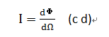
The luminous intensity of an LED refers to the luminous flux emitted per unit solid angle in a given direction:
(c d)
The emission angle (or beam angle) is usually represented by the half-intensity angle θ1/2, that is, the beam angle included when the light intensity is greater than or equal to 1/2 of the peak light intensity in the light intensity distribution.
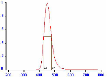
Figure 1 Spectral distribution
iV. Spectral distribution, peak wavelength and bandwidth
The spectral power distribution of an LED determines not only the color of the light emitted, but also its luminous flux and its color rendering index. It is usually represented by the relative spectral power distribution S(λ), as shown in Figure 1. When the spectral power drops to 50% of its value along both sides of the peak, the difference between the corresponding two wavelengths, Δλ=λ2-λ1, is the spectral bandwidth.
v. Chromaticity coordinates, dominant wavelength and color purity
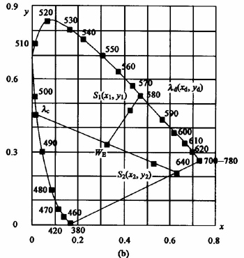
The color of any light source can be represented by a coordinate point (x, y) in the CIE1931XYZ chromaticity system, as shown in Figure 2.
Figure 2 CIE1931XYZ chromaticity system
For color LEDs, the dominant wavelength and color purity can more intuitively express the color characteristics of the light. The dominant wavelength of an LED indicates the hue of a color, while color purity represents how vivid that color is.
vi. Color temperature and color rendering index
When the luminous color of the light source is the same as the color radiated by the black body at a certain temperature, the temperature of the black body is called the color temperature (K) of the light source.
For white LEDs, the luminous color is often not exactly the same as the chromaticity coordinates of a black body (complete radiator) at various temperatures, so it is represented by correlated color temperature (CCT). That is, when the chromaticity of the light source is closest to the chromaticity of the complete radiator at a certain temperature, the temperature of the complete radiator is called the correlated color temperature of the light source.
In addition to the apparent color of LEDs used in lighting engineering, the more important characteristic is often whether the color of the surrounding objects under LED lighting is consistent with the color of the object under complete radiation (such as sunlight). The so-called color rendering properties.
Different applications have different requirements for the color rendering index, as shown in Table 1.
Table 1
CRI
Quality
Applications
100~85
High color rendering
High color rendering occasions
85~75
good color rendering
Indoor lighting
75~50
Generally
public places such as squares
50 and below
poor color rendering
No requirement for color rendering
vii, Photobiological Safety
Before the 20th century, the photobiological safety of lighting sources was not as important as electrical safety, temperature and mechanical safety. In recent years, with the deepening of photobiological research, the photobiological safety of lighting sources has attracted more and more attention. CIE, IEC and various countries have formulated corresponding standards.
The current conventional lighting LED is based on the excitation of phosphors by blue light to generate mixed light to achieve white light. The blue light part of it is the most sensitive area for “retinal blue light hazard”. Therefore, LEDs for lighting should mainly consider the photobiological effect of the blue light part.
3. LED Typical Test Equipment
i. LED chip light emission test
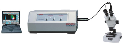
Generally, the area of the LED chip is only on the order of 0.1mm2, so it is necessary to use a special probe to supply power to the LED to make it emit light normally. The luminous brightness on the surface of the LED chip was measured by a microphotometer.
The picture below shows the SPR-920D microspectrometric radiation analyzer, which is used to measure the spectral radiance distribution, chromaticity coordinates, color temperature, color rendering index, color purity, dominant wavelength, luminous brightness and other light and color parameters of the LED light-emitting chip. The instrument adopts the micro-luminescent indicator and three-dimensional micro-motion probe station designed according to the international patent to ensure the accurate positioning of the test chip.
ii. LED Package Test
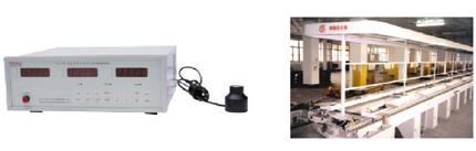
At present, the LED packaging test is divided into two stages. One is the rapid test of photoelectric color on the production line. The required instruments include an electrical performance analyzer (LED101), a smart color analyzer or a fast spectrometer. It is used to quickly test LED’s forward current, voltage, luminous intensity (or light energy), chromaticity coordinates, color temperature, color purity, dominant wavelength and other parameters on the production line. The test system is usually calibrated with standard LEDs, as shown in the figure below.
The other type is laboratory quality testing. Light and color measuring instruments usually use high-precision spectroradiometers, and are calibrated with national metering transfer tungsten filament standard lamps. It can accurately measure LED spectral power distribution, luminous flux, optical power, peak wavelength, bandwidth, chromaticity coordinates, color purity, dominant wavelength, color temperature, color rendering index and other parameters. The light intensity distribution was measured with a variable-angle photometer (PR-108A) that complies with the requirements of CIE127.
LED production line light color tester
iii. Combined LED lamp (apparatus) test
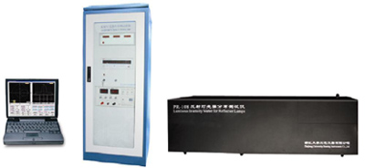
The test of LED reflector lamp (apparatus) can refer to the standard method of IEC. For LED lamps with narrow beams, the length of the photometric arm is required to be more than 20 times larger than the diameter of the light-emitting surface of the lamp. At present, the most commonly used measurement distance is 1m. The picture below is a typical test system, the length of the metering arm can be 1.0m or 2.0m.
LED reflected light intensity distribution tester
iv. Testing of LED Phosphors
As a phosphor for white LEDs, it is necessary to measure parameters such as luminous brightness, spectral power distribution, chromaticity coordinates, color temperature, and color rendering index under the excitation of corresponding blue-violet LEDs. In addition, an LED phosphor thermal quenching characteristic tester can be used to measure the luminous brightness and chromaticity characteristics of LED phosphors at different temperatures.

 (c d)
(c d)