1. Optical Characteristics of LED Light Source
Most of the LED lighting sources currently used are white light generated by exciting YAG phosphors with blue light around 450nm. The ratio and particle size of phosphors are the key materials affecting white LEDs. It also determines the spectral characteristics and also affects the color temperature and light efficiency of the finished product. The spectral characteristics, color rendering index and luminous efficiency of white LEDs are related to YAG phosphors and driving current. Changing any one of them can change its color temperature, and its spectral characteristic curve will also change.
White LEDs with color temperatures of 3000K, 4500K and 6500K have different spectral characteristics. From the spectral curves of the three, it can be seen that the product with the highest color rendering index is the 6500K color temperature product, and the product with the highest light efficiency is also the 6500K product. The lowest color rendering index is the 3000K color temperature product, and the lowest light efficiency is the 4500K test sample.
This set of test parameters shows that the situation of the LED light source is different from that of the traditional light source. The particle size of the phosphor powder and the size of the current drive are all related to the optical parameters. Every small change affects the final parameters.
In order to further understand the characteristics of LED lighting, we analyzed the relationship between light output energy and color temperature for some LED light sources for lighting. We can see that for LED lighting products of the same power, with the increase of color temperature, the light output energy also increases.
2. Heat Dissipation Problem
Although the heat generated by the LED lighting source is smaller than that generated by the traditional light source, a large part of the energy is still converted into heat. According to the statistical analysis of test data, about 70%~75% of the electric power of LED lighting products below 20W is converted into heat energy. For high-power LED lamps, about 70% of the power is converted into heat energy, and the heat is concentrated, resulting in a sharp rise in the P-N junction temperature.
Thermal design limits the maximum junction temperature. In order to ensure the service life, spectral characteristics and delay of light decay of the LED, the junction temperature of the LED needs to be controlled below 80°C.
3. Power Driver
The following figure shows the volt-ampere characteristic curve of a certain type of blue LED. It can be seen from the curve that if a regulated power supply is used, when the voltage applied to both ends of the light-emitting diode fluctuates between 3.0 and 3.6V, its current fluctuation range is 12.5-35mA.
Assuming that the LED’s normal operating current is 12.5mA @ 3V, the drive power is 37.5mW. When the voltage fluctuates to 3.6V, its operating current will rise to 35mA. In this way, the power is increased to 126mW, and the driving power is increased by 2.36 times. This not only requires high overload capacity of the power supply, but also damages the LEDs. Therefore, the LED lighting cannot be powered by a voltage regulator circuit, otherwise the light decay of the LED will be accelerated or damaged.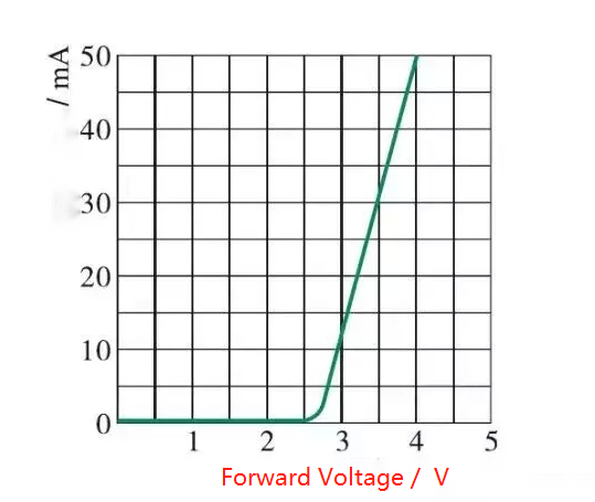
LED volt-ampere characteristic curve.
The constant current driving method is an ideal LED driving method, which can avoid the current change caused by the change of the forward voltage of the LED. At the same time, the constant current stabilizes the brightness of the LED, reducing the redundancy of the driving power. But this can lead to a substantial increase in the cost of the drive.
4. Light Distribution of Lamps
With the development of the LED lighting industry, R&D personnel in the white LED lighting industry have improved the structure of high-power LEDs for lighting. A certain beam angle is generated by the primary light distribution, and then according to the light beam generated by the primary light distribution of the LED light source, the lamp is designed, and the secondary light distribution is carried out, and finally the beam angle is enlarged.
From the comparison test of the illumination uniformity of traditional fluorescent lamps and LED bracket fluorescent lamps, it can be seen that at a height of 1.6m, the illumination at the center of the LED bracket fluorescent lamp is more than 1.5 times higher than that at 1.95m. And as the height increases, the uniformity increases. When it reaches a height of 3m, it is basically in a uniform state.
After continuous improvement, the LED bracket fluorescent lamp has solved the directivity problem and glare problem of a large part of the initial products. However, due to the inherent characteristics of LED light-emitting diodes, under the premise of ensuring high light efficiency and energy saving, the directivity problem cannot be completely eliminated.
At a height of 1.95m, the difference between the central illuminance and the edge illuminance is about 40lx. Although it is difficult for the human eye to recognize, it is impossible to fully achieve the level of non-directionality of traditional fluorescent lamps, and the difference in illuminance is more obvious when the vertical height is less than 2m.
Illumination comparison of LED lamps and fluorescent lamps
Taking the 18W ordinary fluorescent lamp as a comparison, from the analysis of the actual use of ordinary lighting, whether it is in the office or commercial building, the vertical space is 2m or more, and it is impossible to install only a single fluorescent lamp. The interval is generally about 2m, so there will be a complement.
Without considering the lamps, taking the height of 1.95m as an example, whether it is an LED or a traditional fluorescent lamp, the difference between the illuminance at 1m perpendicular to the central axis and the illuminance at the center point is about 15lx. Utilizing lamp-to-lamp illuminance complementarity, LEDs can achieve uniform levels of illumination from conventional fluorescent lamps.
Five Ways to Reduce Output Ripple in LED Design
Output ripple refers to the AC component superimposed on the DC stabilized quantity when the DC power supply is output. Looking at it with an oscilloscope, you will see that the voltage fluctuates slightly up and down, just like water ripples, so it is called ripple. Common ways to suppress or reduce it are as follows:
Increase inductance and output capacitor filtering
According to the formula of the LED driving power supply, the current fluctuation in the inductor is inversely proportional to the inductance value, and the output ripple is inversely proportional to the output capacitance value. Therefore, increasing the inductor value and output capacitor value can reduce the ripple.
Relationship between output ripple and output capacitance:
vripple=Imax/(Co×f)
We can see that increasing the value of the output capacitor reduces the ripple.
The usual practice, for the output capacitor, use aluminum electrolytic capacitors to achieve the purpose of large capacity. However, electrolytic capacitors are not very effective in suppressing high-frequency noise, and the ESR is relatively large, so designers will parallel a ceramic capacitor next to it to make up for the lack of aluminum electrolytic capacitors.
At the same time, when the LED driving power supply is working, the voltage Vin at the input terminal does not change, but the current changes with the switch. The input power supply will not supply current well at this time. Usually close to the current input (in the case of BucK type, near SWITcH), designers use parallel capacitors to supply current.
Secondary filter
The second stage filter is to add another stage of LC filter. The LC filter has obvious suppression effect on noise and ripple. According to the ripple frequency to be removed, select the appropriate inductor and capacitor to form a filter circuit, which can generally reduce the ripple very well. However, in this case, the sampling point of the feedback comparison voltage needs to be considered.
If the sampling point is selected before the LC filter (Pa), the output voltage will decrease. Because any inductor has a DC resistance, when there is current output, there will be a voltage drop across the inductor, causing the output voltage of the power supply to drop. And this voltage drop varies with the output current.
After LED drive power output, connect LDO filter
This is the most effective way to reduce ripple and noise. The output voltage is constant, no need to change the original feedback system. But it is also the method with the highest cost and the highest power consumption. Any LDO has one indicator: the noise rejection ratio. After the LDO, the ripple is generally below 10mV.
Put capacitor C or RC in parallel with diode
When the diode is turned on and off at high speed, parasitic parameters must be considered. During the diode reverse recovery, the equivalent inductance and equivalent capacitance become an RC oscillator, producing high frequency oscillations. In order to suppress this high frequency oscillation, a capacitor C or RC snubber network should be connected in parallel across the diode. The resistance is generally 10Ω-100Ω, and the capacitor is 4.7pf-2.2nf.
The capacitor C or RC connected in parallel on the diode can be determined by trial and error. If it is not selected properly, it will cause more serious oscillation.
Diode followed by inductor (EMI filtering)
This is also a commonly used method to suppress high-frequency noise. According to the frequency that generates noise, selecting an appropriate inductive element can also effectively suppress noise. It should be noted that the rated current of the inductor must meet the actual requirements.


