Excellent lighting design and advanced lighting equipment allow us to enjoy the comfort and convenience brought by lighting. But the glare problem has always been a big headache.
What is glare? Why does glare occur? How to reduce or even eliminate glare?
Glare: A visual phenomenon that causes an uncomfortable feeling or reduces the ability to observe details or objects due to an unsuitable distribution or range of brightness in the field of view, or the presence of extreme contrast.
Glare is an undesirable visual phenomenon that can make people feel dazzling, causing eye soreness, tearing, reduced vision, and possibly even temporary loss of vision.
The mechanism by which glare reduces visual function can be understood as follows: the light emitted by the glare source is scattered in the direction of the retina to form a bright light curtain, which is superimposed on the clear scene image. This light curtain has an equivalent veiling luminance, which is equivalent to increasing the brightness of the background and decreasing the contrast, making people feel glare and making it difficult to see the target.
2. Definition of Terms Related to Glare
(1) Visual field:
When the eyes are fixed on a target, objects in a certain space beyond the fixation point can also be seen. This spatial range is called the field of view. The field of view is divided into horizontal field of view and vertical field of view, reflecting the visual recognition range of the human eye in the horizontal and vertical directions.
Under static conditions, the horizontal field of vision of both eyes can reach 160 degrees and the vertical field of view can reach 50 degrees. In a moving vehicle, the driver’s dynamic field of view is related to the speed of the vehicle. The faster the speed is, the farther the attention point is, the smaller the field of view, and the surrounding scenery is difficult to see clearly.
Traffic psychology research shows that the vehicle speed is 40km/h, and the horizontal dynamic field of vision is 100 degrees. The vehicle speed is 70km/h, and the horizontal dynamic field of view is 65 degrees. The vehicle speed is 100km/h, and the horizontal dynamic field of view is 40 degrees. The vertical motion field of view, that is, the visual recognition space of the driver’s line of sight in the vertical direction, is usually 30 degrees.
Affected by human eye parallax and poor lighting conditions, the human eye’s ability to correctly distinguish colors in a dark environment is very poor. Therefore, visual discrimination depends on the difference in brightness between an object and its background. An object can only be seen when a certain brightness contrast is obtained.
(2) Luminance contrast:
C=⊿L/Lb =∣Lo-Lb∣/Lb
In the formula, ⊿L——the difference between the brightness of the recognition object and the brightness of the background;
Lo – Recognized object brightness (cd/㎡);
Lb – background brightness (cd/㎡).
Brightness contrast is divided into “positive contrast” and “negative contrast”. Positive contrast is when the object brightness is higher than the background brightness; negative contrast is when the object brightness is lower than the background brightness.
(3) Critical (threshold) contrast Ct:
Ct = ⊿Lt /Lb
In the formula, ⊿Lt——critical brightness difference, the brightness difference between the target and the background when the human eye can just recognize the target.
(4) Visibility level VL:
The ratio of the actual brightness contrast C of the target and the background to the critical contrast Ct.
VL=C/Ct=⊿L /⊿Lt
Glare can be divided into discomfort glare and disability glare according to the degree of influence.
(5) Discomfort glare:
Refers to glare that makes people’s eyes feel uncomfortable in the field of view, but does not necessarily reduce the visibility of visual objects. This glare is also known as psychological glare.
(6) Disability glare:
It is the glare that reduces people’s visual function in the field of vision. It is a glare that reduces the visibility of visual objects, but does not necessarily create an uncomfortable feeling.
According to its formation mechanism, glare can be divided into direct glare, interference glare, reflected glare, and contrast glare.
(7) Direct glare:
Glare caused by luminaires present in the field of view, especially close to the line of sight.
(8) Disturbance glare:
Glare caused by a luminous body when there is a luminous body in a direction other than the viewing object.
(9) Glare by reflection:
Glare caused by reflections in the field of view, especially when a reflected image is seen near the line of sight.
(10) Comparison glare:
There is glare caused by excessive brightness contrast in the light environment.
3. Evaluation Mthod of Glare
So far, people have summarized the following four main glare evaluation expressions for lighting occasions such as indoor environments, stadiums, and motor vehicle roads:
(1) Unified glare value UGR
Calculation of unified glare rating UGR:
In the formula, Lb——background brightness (cd/㎡);
La – the brightness of each luminaire in the direction of the observer (cd/㎡);
ω——The solid angle (sr) formed by the light-emitting part of each luminaire to the observer’s eyes;
P – Position index for each individual luminaire.
The above parameters should be determined according to the following formulas and regulations:
(i) Lb=Ei/π
In the formula, Ei——indirect illuminance (Lx) in the direction of the observer’s eyes.
(ii) La =Ia/A·cosα
In the formula, Ia – the luminous intensity of the lamp in the direction of the observer’s eyes (cd);
A·cosα——the projected area of the lamp in the direction of the observer’s eyes (㎡);
α——The angle (°) between the surface normal of the luminaire and the direction of the observer’s eyes.
(iii) ω=AP /r2
In the formula, AP——the apparent area of the light-emitting part of the lamp in the direction of the observer’s eyes (㎡);
r —— the distance (m) from the center of the light-emitting part of the luminaire to the observer’s eyes.
The application conditions of the unified glare value UGR:
(i) UGR is suitable for general lighting fixture designs for simple cube-shaped rooms, not for rooms with indirect lighting and illuminated ceilings,
(ii) Applicable to the case where the solid angle formed by the light-emitting part of the lamp to the eyes is 0.1sr>ω>0.0003sr,
(iii) luminaires of the same type are arranged evenly and equally spaced,
(iv) the luminaire has a double symmetrical light distribution,
(v) The height of the eyes of a sitting observer is usually taken as 1.2m, and the height of the eyes of a standing observer is generally taken as 1.5m,
(vi) The observation position is generally at the midpoint of the longitudinal and transverse walls, with the line of sight level facing forward,
(vii) The room surface is the work surface approximately 0.75m above the ground, the lamp installation surface and the wall between these two surfaces.
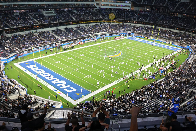
(2) Glare value GR
Calculation of the glare rating (GR) of outdoor sports venues:
In the formula, Lv1——the brightness of the light curtain generated by the light emitted by the lamp directly to the eyes (cd/㎡);
Lve – The brightness of the light curtain (cd/㎡) produced by the light directly incident to the eye caused by the environment.
The parameters in the formula should be determined according to the following formulas:
In the formula, Eeyei——the illuminance on the observer’s eyes, the illuminance is the illuminance (Lx) generated by i light sources on the vertical plane of the line of sight;
θi – the angle (°) formed by the observer’s line of sight and the direction in which i light sources are incident on the eyes;
n——The total number of light sources.
2) Lve =0.035Lav
In the formula, Lav——the average brightness of the visible horizontal illumination field (cd/㎡).
Lav =Ehorav · ρ/πΩ0
In the formula, Ehorav——the average horizontal illuminance of the irradiation site (Lx);
ρ——the reflectance of the area during diffuse reflection;
Ω0 – 1 unit solid angle (sr).
Application conditions of glare value GR:
(i) This calculation method is used for various lighting arrangements in outdoor sports venues that meet the uniformity of illuminance under common conditions.
(ii) for use where the line of sight is below eye level,
(iii) the background seen is the field being photographed,
(iv) The observer position for the calculation of the glare value may be the grid position for calculating the illuminance, or the standard observer position,
(v) A certain number of viewing directions can be selected by rotating at a certain number of angular intervals (5°…45°).
(3) Threshold increment TI for road lighting glare evaluation
Threshold increment is a measure of disabling glare. It is expressed as the percentage that the brightness contrast between the object and its background needs to be increased in order to achieve the same purpose of seeing the object when there is a glare source.
The threshold increment is to use the average road surface brightness as the background brightness. When the background brightness range is 0.05cd/㎡< Lb <5cd/㎡, the calculation formula of TI is approximately:
TI=65Lv/Lav0.8(%)
In the formula, TI—threshold increment (%);
Lv—equivalent light curtain brightness (cd/㎡), assuming that the observer always looks at the front parallel to the road axis at an angle of 1° to the horizontal line (that is, always looks at a point on the road about 86 meters ahead of it);
Lav—The average brightness of the road surface (cd/㎡).
The calculation formula of the equivalent light curtain brightness Lv:
Lv=10∑(Eeyei/θi2)
In the formula, Eeyei—the vertical illuminance (Lx) of the i-th lamp in the eyes of the observer;
θi—the angle (°) between the luminous center of the i-th luminaire and the observer’s line of sight. (1.5°< θ <60°)
Threshold increment TI can also be directly measured with a dedicated imaging photometer.
The average brightness Lav of high-grade road pavement is usually 1.0~2.0cd/m2, and the threshold increment TI is required to be below 10%, so when Lav is 1.0cd/m2, the equivalent light curtain brightness Lv should not be greater than 0.15cd/m2. When Lav is 1.5cd/m2, the equivalent light curtain brightness Lv should not be greater than 0.20cd/m2. When Lav is 2.0cd/m2, the equivalent light curtain brightness Lv should not be greater than 0.25cd/m2.
Lv is the summation of 10Eeye/θ2 of all lamps with an included angle of 1.5 degrees to 60 degrees with the viewing target. In the case of lamp arrangement, that is, all angles of θ are constant, the smaller the Eeye, the better.
(4) Glare control level G in road lighting
In road lighting, the uncomfortable glare felt by the driver can be measured by the glare control level G. The G value is related to the nature and arrangement of the lamp itself.
Factors affecting glare control grade G include:
(a) As regards lamps and light sources:
(i) In the C-γ system, the absolute light intensity of C=0, γ=80°, that is, in the vertical plane parallel to the axis of the road, from the lowest point of the luminaire, the light intensity in the direction of 80°, Namely I80.
(ii) The ratio of the absolute light intensity in the direction of C=0, γ=80° to the absolute light intensity in the direction of C=0, γ=88°, namely I80/I88.
(iii) The luminous area of the luminaire seen in the direction of 76° from the vertical directly below the luminaire, namely F.
(iv) The color coefficient of the light source used, expressed in C. When the light source is a low-pressure sodium lamp, C=0.4; when a high-pressure sodium lamp is used, C=0.1; when a high-pressure mercury lamp is used, C=-0.1; when other light sources are used, C=0.
(b) In terms of facility layout:
(i) Average road brightness, ie Lav.
(ii) The height of the horizontal line of sight (1.5m) from the luminaire, i.e. h’.
(iii) The number of lamps per kilometer, i.e. p.
The relationship between these parameters and the glare control level G is as follows:
It should be noted that each parameter in the above formula is only suitable for the following ranges:
50cd≤I80≤7000cd;
1≤I80/I88≤50;
0.007m2≤F≤0.4m2;
0.3cd/m2≤Lav≤7cd/m2;
5m≤h’≤20m;
20≤p≤100.
Strategies for Glare Control
From the above glare evaluation formulas, the direction of the glare control strategy can be summarized:
(1) Increase the background brightness in the field of view, because the glare value is generally inversely proportional to the background brightness. But it should be achieved by improving the lighting efficiency of the system, rather than simply increasing the power consumption.
(2) Reduce the vertical illuminance generated by the lamp in the observer’s eyes, thereby reducing the equivalent light curtain brightness generated by the glare source in the observer’s eyes.
(3) Increase the angle between the viewing target and the light-emitting surface of the lamp as much as possible. This involves the reasonable arrangement of lamps and lanterns.
(4) Reduce the brightness of the light-emitting surface of the lamp.
(5) Set up scientific light-cutting facilities.
Summary
In most cases, glare will have a negative impact on the lighting effect, and even directly lead to the failure of the lighting design. Our goal is to seek a solution that can reasonably suppress glare, efficiently utilize the luminous flux of the light source, and improve the effective utilization of energy. Therefore, scientific lighting design is very important.