What is the Volt-ampere Characteristic of LED
What kind of technology should be used for dimming LED light sources? How do we master it? To answer the above questions, we must first understand the volt-ampere characteristics of LEDs.
The so-called volt-ampere characteristics of the LED is the characteristic of the current flowing through the LED P-N junction with voltage. The oscilloscope can show this change very vividly.
A complete volt-ampere curve includes forward and reverse characteristics. Generally, the reverse characteristic curve changes steeply. When the voltage exceeds a certain threshold, the current will rise exponentially, thereby breaking down the LED P-N junction.
The forward voltage of the LED is also determined by its forward current. From the volt-ampere characteristics of the LED, the change in the forward current will cause a corresponding change in the forward voltage. To be precise, a decrease in the forward current will also cause a decrease in the forward voltage.
Therefore, when the current is lowered, the voltage of the LED will also decrease, which will change the relationship between the power supply voltage and the load voltage.
Therefore, from the volt-ampere characteristics of the LED, we know that the dimming of the LED light source cannot be achieved simply by reducing the input voltage or input current of the LED. In addition, the waveform of the sine wave of the LED is different from that of the incandescent lamp, so it is impossible to simply change its conduction angle to achieve the purpose of changing its effective value (effective dimming).
Examples of Volt-Ampere Characteristics
In order to make it easier for everyone to understand the above characteristics, examples are as follows:
For example, in an LED lamp with an input of 24V, 8 1W high-power LEDs are connected in series. When the forward current is 350mA, the forward voltage of each LED is 3.3V, so 8 pieces in series are 26.4V, so the load voltage is higher than the input voltage. Therefore, engineers should use a constant current source >24V at the beginning of the design.
However, in order to dimming, the current is reduced to 100mA. At this time, the forward voltage is only 2.8V, and the 8 series are connected to 22.4V, and the load voltage becomes lower than the input voltage. In this way, the constant current source of >24V will not work at all, and finally the LED will flicker.
At this time, you may choose a step-down (wide voltage) constant current source. For example, a 10V-30V constant current source is used for dimming, but if this step-down (wide voltage) constant current source is adjusted to a low forward voltage, the load current of the LED will also become very low.
Therefore, the step-down ratio is very large, which exceeds the normal working range of this step-down (wide voltage) constant current source, and will also make it unable to work and cause flicker.
Characteristics of Constant Current
In addition, the step-down (wide voltage) constant current source can work at low brightness for a long time, which will reduce its efficiency and increase its temperature rise and fail to work. Because the efficiency of the step-down (wide voltage) constant current source is related to the step-down ratio. The greater the step-down ratio, the lower the efficiency, and the greater the power loss on the chip, which will damage the life of the constant current source and the LED light source.
Because many people don’t understand the problem, they always try to find the problem in the dimming circuit, which is useless.
SCR dimming
Ordinary incandescent lamps and halogen lamps usually use thyristors for dimming. Because incandescent lamps and halogen lamps are purely resistive devices, they do not require the input voltage to be a sine wave. Because its current waveform is always the same as the voltage waveform, no matter how the voltage waveform deviates from the sine wave, as long as the effective value of the input voltage is changed, the light can be dimmed.
However, the adjustment of the LED light source by the thyristor dimming will cause unexpected problems. That is, the LC filter at the input will cause the thyristor to oscillate. This oscillation is indifferent to the incandescent lamp, because the thermal inertia of the incandescent lamp makes this oscillation invisible to the human eye. However, audio noise and flicker will be generated for the driving power of the LED.
In addition, the thyristor dimming will destroy the waveform of the sine wave, thereby reducing its power factor value (usually less than 0.5). Therefore, the thyristor dimming greatly reduces the system efficiency of the LED. Moreover, the thyristor dimming waveform increases the harmonic coefficient, and the non-sinusoidal waveform will cause serious interference signals (EMI) on the line to pollute the power grid. In severe cases, it may even paralyze the power grid.
PWM (Pulse Width Modulation) dimming method
Reading here, you may ask: “Lower voltage or current and thyristor dimming methods are not suitable for LED light source dimming, so what is the most suitable method?”
Is it an analog (1-10V) dimming method? No. Analog dimming faces a severe challenge, which is the output current accuracy.
Almost every LED driver needs some kind of series resistance to distinguish the current, and the tolerance, offset and delay in the analog (1-10V) dimming drive result in a relatively fixed error. This will in turn reduce the accuracy of the output current, and the final output current cannot be specified, controlled or guaranteed.
Therefore, to ensure the dimming effect of the LED light source, one of the important points is to reduce the output current error and improve the current accuracy in a closed loop system.
The working principle of PWM (Pulse Width Modulation) dimming method
The PWM (Pulse Width Modulation) dimming method can solve the above problems very well. Because LED is a diode, it can achieve fast switching, and its allowable switching speed can be as high as microseconds or more, which is unmatched by any light-emitting device.
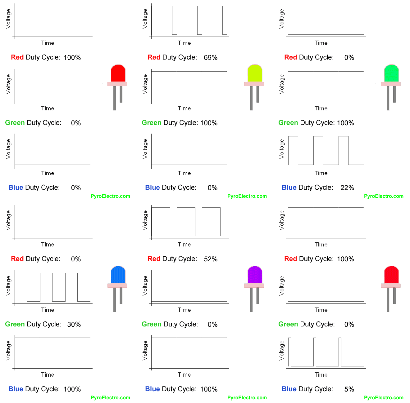
Therefore, as long as the power supply is changed to a pulse constant current source, the brightness can be changed by changing the pulse width. This method is called pulse width modulation (PWM) dimming.
This dimming method is like a sluice that opens and closes in microseconds or more. Since the switching frequency of the sluice gate is so fast that we can’t recognize its switching state with the naked eye, as a result, we can only recognize the switching frequency of its switching frequency through the amount of downstream water.
In addition, because the sluice changes the duty cycle of the output water flow (effective water flow), it does not change the instantaneous water pressure and instantaneous flow rate of the water flow, so the opening and closing action of the sluice gate for more than microseconds will not affect the work of hydroelectric power generation. Because the instantaneous water pressure and instantaneous flow are unchanged, what changes is the amount of downstream water and the total amount of power generation.
Therefore, the PWM (pulse width modulation) dimming method does not change the instantaneous voltage and instantaneous current of the input LED PN junction, but changes the duty cycle of the output current, thereby changing its brightness.
Advantages of PWM (Pulse Width Modulation) dimming method
The LED PWM (Pulse Width Modulation) dimming method has the following advantages:
- There will not be any LED chromatogram shift, because the LED always works between the full amplitude current and 0.

- It has a very high dimming accuracy, because the pulse waveform can be controlled to a high precision, so it is easy to achieve a precision of one ten thousandth.
- Even if the light is dimmed in a wide range, there will be no flicker. Because the working conditions (boost ratio or buck ratio) of the constant current source will not be changed, problems such as overheating are less likely to occur.
- It can be combined with digital (DALI/DSI/DMX 512) control technology for control, because the digital control signal can easily be transformed into a PWM signal.
The disadvantages of PWM (Pulse Width Modulation) dimming method
Although the LED PWM (Pulse Width Modulation) dimming method has many advantages, the following two issues need to be paid attention to:
- The choice of pulse frequency. Because the LED is in a fast switching state, if the operating frequency is very low, the human eye will feel flicker. In order to make full use of the residual visual phenomenon of the human eye, its operating frequency should be higher than 100 Hz, preferably 200 Hz.
- Eliminate howling caused by dimming. Although the human eye cannot detect above 200Hz, it is within the range of human hearing until 20kHz. At this time, it is possible to hear the slightest voice. There are two ways to solve this problem. One is to increase the switching frequency above 20kHz, out of the range of human hearing. Another method is to find out the sound-producing device and deal with it.
At present, some manufacturers of LED dimmable power supplies, drivers and digital control systems have solved the above problems very well.
For example, Tridonic’s LED dimmable power supplies and drivers all use PWM (Pulse Width Modulation) dimming technology. Its control signals adopt DALI (Digital Addressable Lighting Interface) technology, combined with a digital lighting control system, to realize a fully digital LED control product line.
In addition, TRIDONIC’s latest LED light engine products are based on PL-LED technology. PL-LED refers to TRIDONIC’s innovative LED phosphor technology, which can realize the change of color and color temperature within the same LED light source. At the same time, a fixed color temperature (for example: 2700K-6200K) or color (for example: RGB) can be selected through software and dimming control, which is the highest state of LED application digital dimming technology.
DALI dimming technology
The advantages of DALI dimming technology
Good LED light source dimming technology requires good LED control signal technology to match and cooperate in order to become an effective, stable and reliable system. As mentioned earlier, the LED PWM (Pulse Width Modulation) dimming method has an outstanding advantage, that is, the digital control signal can easily be transformed into a PWM signal.
In the digital control signal of lighting, DALI (Digital Addressable Lighting Interface) has the unparalleled superiority of other lighting digital control signals. It is also the mainstream application of digital control signals in the lighting industry, which is an open international standard.
Therefore, the matching of PWM (Pulse Width Modulation) dimming mode and DALI (Digital Addressable Lighting Interface) can be described as “a good horse with a good saddle”, and each exerts its own advantages. PWM (Pulse Width Modulation) dimming technology solves the final dimming problem of LED light sources, while DALI (Digital Addressable Lighting Interface) technology solves the control, feedback and networking of each LED lamp.
Characteristics of DALI dimming technology
The biggest feature of DALI (Digital Addressable Lighting Interface) technology is that a single lamp has an independent address. Through the DALI system software, a single lamp or any lamp group can be accurately dimmed and switched, regardless of whether the lamps are in the same circuit or different circuits on the strong current.
That is, the lighting control has nothing to do with the strong current circuit. DALI system software can independently address single or multiple lamps on the same strong current circuit or different circuits, so as to realize individual control and arbitrary grouping.
This concept brings great flexibility to lighting control. Users can freely design lighting schemes that meet their needs according to their needs, and can modify the control requirements arbitrarily even during the operation after the installation, without any changes to the circuit.
Application advantages of combining PWM and DALI
1. The design is simple and easy to implement:
In the design, as long as they are connected to each other through the digital signal interface, they are connected in parallel to the 2-core control line. All groups and scenes can be programmed by computer software during installation and debugging. It not only saves wiring costs, but also only needs to change the software settings without rewiring for design modification, re-layout and separation, which is very simple and easy.
2. Simple and economical installation:
The DALI control line has no special requirements on the wire, and there is no polarity requirement during installation. Only the main power line and the control line are required to be isolated. The control line does not need to be shielded. It should be noted that when the current on the control line is 250mA and the line length is 300 meters, the voltage drop does not exceed 2V. The control line and the power line can be parallel, no need to bury the line separately. The compact design of the control components does not require a special control cabinet, so installation is simple and economical.
3. Simple and convenient operation:
The PWM LED driver with DAL I control interface can automatically handle filament preheating, ignition, dimming, switching, fault detection and other functions. The user interface is very friendly, and the user can operate and control without having a deep understanding of it. For example, if a command to change the current scene is sent, each relevant LED driver calculates the dimming rate according to the difference between the current brightness and the required brightness of the scene to achieve that all LED light sources are synchronized to the required scene brightness.
4. Control is accurate and reliable:
DALI is a digital signal, which is different from an analog signal. The signal of 1010 can realize disturbance-free control and will not distort the control signal due to long-distance voltage drop. Therefore, even if the DALI digital signal control line and the strong wire are in the same line tube, it will not be disturbed. The DALI signal is two-way transmission, which not only transmits control commands forward, but also feeds back the information of the LED driver’s status, fault information, switch, and actual brightness value to the system.
5. Wide range of applications:
Nowadays, DALI interface is not only used for fluorescent lamp ballast dimming, various electronic transformers for tungsten halogen lamps, electronic ballasts for gas discharge lamps, and LEDs also use DALI interface dimming.
The control equipment also includes: a radio receiver, a relay switch input interface. Various key control panels, including LED display panels, already have DALI interfaces, which will make the application of DALI more and more widespread. The controller is expanded from the smallest office to a multi-room office building, from a single store to a star hotel.


