This article introduces a variety of driving methods for high-power and high-brightness LEDs. The following tasks need to be completed to build an LED-based system:
Determine the number of LEDs used and the connection scheme between the LEDs,
Choose linear mode or switch mode to drive LED,
Select the power supply, that is, DC voltage, AC power or battery,
Optical sub-systems such as lenses, surface filters, etc.
The number of LEDs depends on the requirements for brightness and the drive current of the LEDs. The introduction to the optical system is not covered in this article.
LED Connection Scheme
When the number of LEDs is greater than one, a LED connection scheme must be determined. There are no hard and fast rules when choosing a connection plan, sometimes it’s just a matter of preference. Sometimes the connection scheme of the LED can be determined according to the selection of the driver. Sometimes the available power supply and required performance will also affect the choice of connection scheme.
The connection of LEDs is generally divided into three main structures, namely series, parallel (common anode, common cathode, common anode and common cathode), and series, parallel hybrid (2 LEDs in series, N LEDs in parallel)
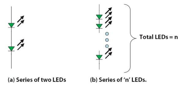
1. in series
Figure 1 shows the series circuit of LEDs. The LED currents in the series circuit are equal everywhere. The advantage of series connection is that if one of the LEDs is open, none of the LEDs will emit light. The total VF at both ends of the series becomes larger, but the demand for current becomes smaller. The LED voltage output by the LED drive circuit must be greater than the total VF voltage in the series. Generally, the closer the rated LED output voltage is to the total VF voltage in the series, the greater the efficiency of the LED.
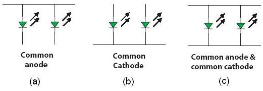
2. Common anode parallel or common cathode parallel
When the current of each LED needs to be adjusted independently, a common anode or common cathode is used in parallel. The advantage of parallel connection is that when one LED is open, it will not affect other LEDs. The disadvantage of parallel connection is that the circuit requires a higher rated current.
3. Common anode in parallel and common cathode in parallel
The difference between the LED turn-on voltages will cause current variability. This can be avoided by using a minimum number of LEDs with matching characteristics (electrical characteristics, thermal characteristics, and service life). Putting several LEDs with matching characteristics together is equivalent to a larger LED with a higher rated current. Due to different aging characteristics and thermal characteristics, these matched LEDs may gradually differentiate.
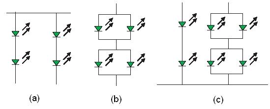
4. Serial and parallel hybrid connection
Figure 3 is an example of a series-parallel hybrid. This connection scheme is usually a compromise between the total VF demand and the total current demand, so it is more suitable for effective LED driving.
LED Drive Circuit
The connection scheme will affect the number of drive channels required. Most LED drivers generally have only one channel. However, some multi-channel LED drivers are also available. In a common anode or common cathode structure, each channel can control a single LED in series or a single branch in parallel LEDs. To drive LEDs in series, the following conditions must be met:
The output LED drive voltage must be greater than the total VF voltage of the series LED,
The LED drive constant current output must be greater than or equal to the current required by the LED. If the current is large, PWM can be used to reduce or change the circuit current, such as a sensing resistor. Generally, LED drivers are divided into linear LED drivers and switch-mode LED drivers.
Linear LED drivers are less efficient and usually take up a lot of space. Switch mode LED drivers are more efficient and smaller. However, they all have problems with electrical noise and radiated noise, and their designs are complicated.
When the input supply voltage is lower than the total VF of the LED, a switch-mode LED driver must be used. Whether to choose a linear LED driver or a switch-mode LED driver can be directly determined according to their effective supply voltage and work efficiency.
Turn the voltage regulator into an LED driver
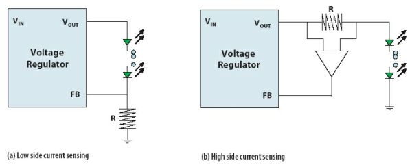
A standard regulator has the following pins, VIN, GND, VOUT, and FB. The FB pin controls the output voltage of the regulator by detecting an input voltage. For constant current LED drivers, current detection is necessary. By inserting a resistor in the current path of the LED, the LED current is converted into a measurable voltage on the FB pin. Usually the resistor is inserted on the cathode side of the LED to measure the low-end voltage, otherwise the resistor can only be inserted on the anode side of the LED to measure the high-end voltage. At this time, a differential amplifier with a high common-mode rejection ratio is needed to measure the voltage across the resistor.
The low-voltage side resistance value is VFB/ILED, and the high-voltage side resistance value is VFB/(ILED×AV).
Among them, VFB is the calibration feedback voltage of the FB pin, ILED is the current required by the LED, and AV is the gain of the differential amplifier.
For linear LED drivers, the number of LEDs being driven is:
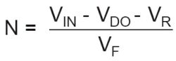
For switching LED drivers, the number of LEDs being driven is:
Among them, VIN is the input supply voltage. VDO is the voltage difference between input and output. VR is the detection voltage across the resistor. VOR is the rated output voltage of all LEDs connected in series. VF is the standard single LED turn-on voltage.
Example of Linear LED Driver
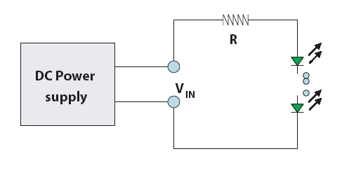
1. Single resistor current limit
A resistor is used to limit the DC supply current of the LED. The advantage of single-resistor current limiting is that the structure is simple, but the LED current is not stable due to the drift of the on-voltage of the LED.
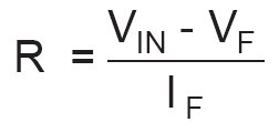
The resistance is:.
Among them, VF is the voltage of several LED strings, IF is the current of the LED, and VIN is the input voltage.
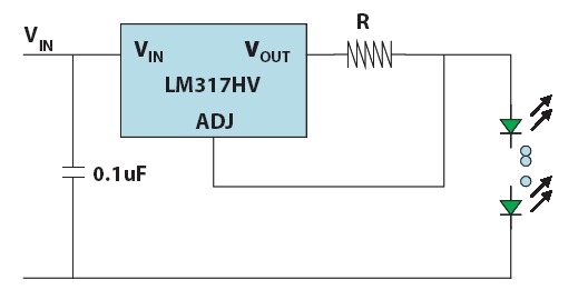
2. LM317 or LM317HV
As shown in Figure 6, the LM317HV regulator is used as an LED driver.
LM317HV stabilizes the voltage between ADJ and OUT at 1.23V. At this time, the current of the LED is ILED=1.23/R.
Compared with a single-resistance driver, the advantage of this circuit is that although the on-voltage of the LED will drift, the LED current will remain constant.
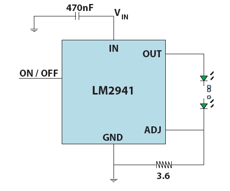
3. LM2941
The other driver LM2941 is similar to LM317. The maximum input voltage of the LM2941 regulator is 26V. LM2941 stabilizes the voltage between the ADJ and GND terminals at 1.275V. As shown in Figure 7, the LED driver LM2941 provides a drive current of 354mA.
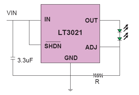
4. LT3021
Another linear regulator is the LT3021. Its maximum input voltage is 10V, and its maximum current rating is 500mA. LT3021 stabilizes the voltage between the ADJ and GND terminals at 0.2V. The LED current is R/0.2, and the breaking voltage is 160mV. If the VF of the LED is 3.6V, the number of LEDs in series is 2.
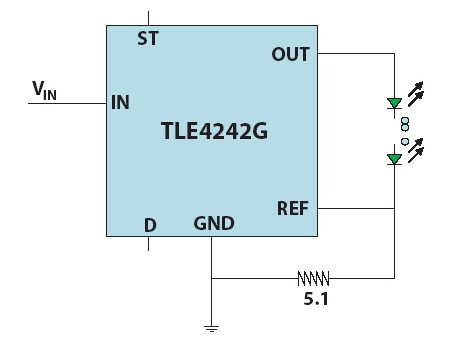
5. TLE4242G
VREF stabilizes the voltage between the ADJ and GND pins at 177mV. The maximum input voltage rating is 42V, and the breaking voltage is 0.7V. The LED current in this circuit is VREF/R. In the circuit of Figure 9, R=5.1ohm, and the LED current is 347mA.
6. AS3691 and AS3692
The rated voltage of AS3691 is 15V, and the maximum LED current is 400mA. AS3692 is similar to AS3691. The difference between them is that the rated voltage of AS3692 reaches 50V, but the maximum LED current is only 200mA.
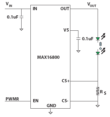
7. MAX16800 LED driver
The rated voltage of this LED driver is 40V, and the driver keeps the voltage between CS+ and CS- stable. The current is set by the external circuit resistance (RS=VSENSE/ILED). In the LED color control application of ADJD-J823 and HDJD-J822, the PWM signal output by ADJD-J823/HDJD-J822 is connected to the EN input of MAX16800.
Switch mode LED driver
The switch mode LED driver is related to the topology of the switching regulator. The switching regulator can maintain a constant voltage under different current loads. No matter what on-voltage the LED needs, the switch-mode LED driver can deliver a constant current to the LED, and provide over-voltage protection or ensure that the rated power limit is not exceeded.
The following are some examples of common switch-mode LED driver topologies:
BUCK step-down regulator, the output voltage is lower than the input voltage,
BOOST boost regulator, the output voltage is higher than the input voltage,
BUCK-BOOST buck/boost regulator, the output voltage is reversed,
SEPIC is similar to a buck/boost regulator, but the output voltage is not reversed,
FLYBACK buck/boost regulator, in which the inductance is replaced by a transformer.
The designer can obtain the relevant information of the IC data sheet and application description from the manufacturer, and work closely with the LED driver manufacturer. We should connect the LED before turning on the switch mode LED driver.
An open switch mode LED circuit will cause the output voltage to rise to the maximum limit and may exceed the limit of the maximum voltage rating of the LED driver.
Example of Switch Mode LED Driver
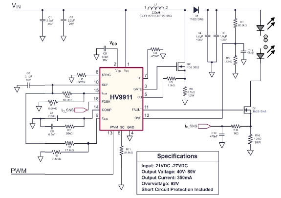
1. HV9911 step-down topology
Provide 21~27V input voltage between VIN and GND. Boost topology circuit provides a maximum output voltage of 80V. The number of InGaN InGaN LEDs that can be driven is ~20. If we do not use PWM, VDD we need to connect VDD to start the LED driver.
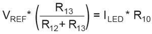
The LED current is:
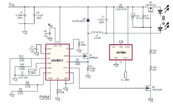
2. HV9911 boost topology
This step-down topology circuit can withstand 130~200V DC voltage input between VIN and GND, and provide 20 to 100V LED output voltage. The high-side current detection limits the LED current to 350mA. If we do not use PWM , we need to connect VDD to start the LED driver.
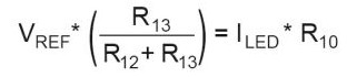
At this time, the LED current is:
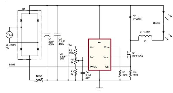
3. HV9910
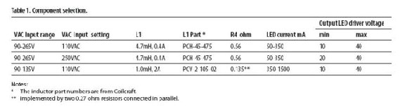
This step-down topology circuit is not isolated from the line voltage. We must connect the LED to the driver before we turn on the AC power. Table 1 shows the reasonable input range of the AC voltage of this circuit. The parameter values of the components L1 and R4 are determined by the LED operating current. Assuming that the LED turn-on voltage is 3.6V, it can drive about 11 LEDs at most.
Figure 13 lists the component parameters of rows 1 and 2. The control PWM signal must work separately from the main line. If PWM is not in use, we need to connect VDD to start the LED driver. Whether you need to try any measuring instrument, you must use an isolation transformer for isolation.
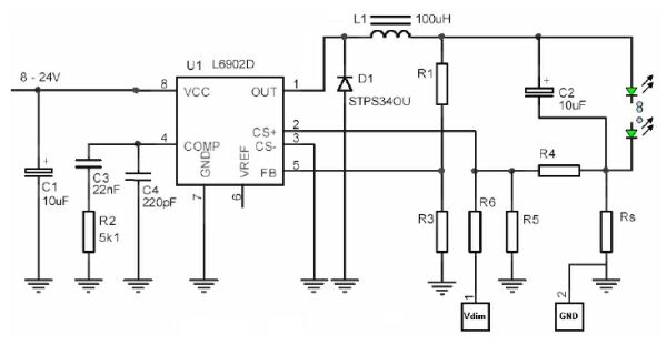
4. ST L6902
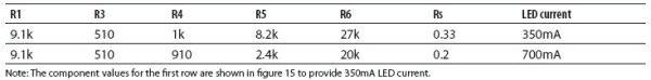
This is a step-down LED driver. Table 2 shows the component parameters required for different LED currents. Note: The components in Figure 15 can provide 350mA of LED current using the component parameters shown in the first row.
The Vdim base provides an input voltage that users can use for linear adjustment or reverse logic PWM adjustment. At 0V, the LED current is maximum. When the voltage increases from 0V to 3.3V, the LED current will also linearly decrease from the maximum value to 0V. Resistors R1 and R3 provide 23.3V over-voltage protection to prevent open circuit in the LED output position. Assuming that InGaN LED VF=3.6V, up to 6 InGaN LEDs can be connected.
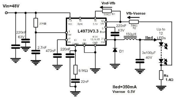
5. ST L4973
This is a step-down topology LED driver. The input voltage is 48V. Up to 12 InGaN LEDs can work in a group. The resistance R1, R2 and the internal 5.1V power supply reduce the detection voltage to 0.5V.
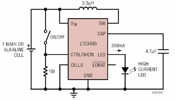
6. LTC3490
This circuit can use a single battery to drive an InGaN LED. The LED output current is limited to 350mA by an internal sensing resistor. If we disconnect the LED pin , the output voltage will be as low as to 4.7V.
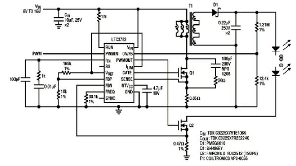
7. LTC3783
This flyback LED driver can provide 150mA current for series LEDs. The overvoltage protection starts at 130V and closes at 120V. The number of serially connected LEDs is 120/3.6=33 LEDs. The PWM signal provides brightness adjustment.
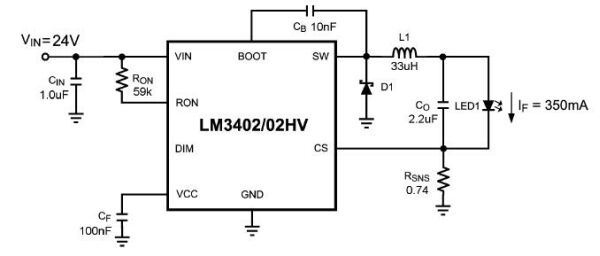
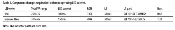
8. LM3402
This is a buck Buck LED driver. It has a constant synchronization structure and engineers have designed the circuit to drive a single INGAN LED. Table 3 shows the changes in component parameters when driving 10 LEDs in series.
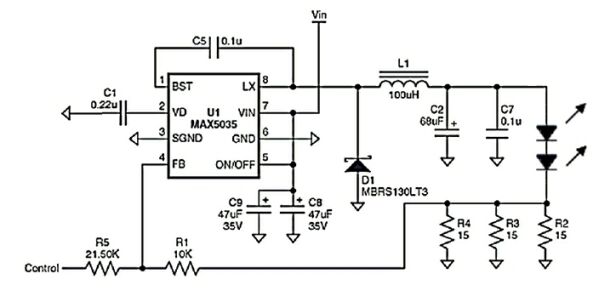
9. Maxim 5035
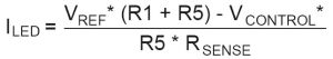
The VIN in this Buck topology circuit can withstand a voltage of 7.5~30V. The LED current is 350mA. The LED output voltage rating is 12V. Can drive 1~3 InGaN LEDs. VCONTROL is a linear regulation input, and the LED current is given by the following equation.
Note: RSENSE is the equivalent value of R2, R3 and R4 in parallel. VREF is generally 1.22V. VCONTROL is the external linear regulation voltage, the LED current is the maximum when this voltage is 0V.
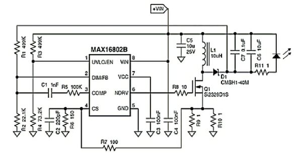
10. MAX16801/MAX16802
MAX16801 is suitable for rectifying AC voltages from 85VAC to 265VAC. MAX16802 is suitable for low-voltage DC input voltage. Figure 21 shows an example of a MAX16802 driver. Engineers have desinged the circuit to drive a single InGaN LED at 350mA. The DC input voltage ranges from 10.8 to 24V. If you want to know other structures, please refer to AN3639 in the design method. Resistor R1 and R2 make the output voltage stuck at 29V.