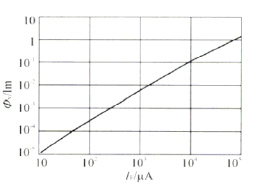
Since the light characteristics of LEDs are usually described as a function of current—the relationship between luminous flux (φV) and IF—rather than a function of voltage, driving with a constant current source can better control brightness.
Characteristics of Super Bright LEDs
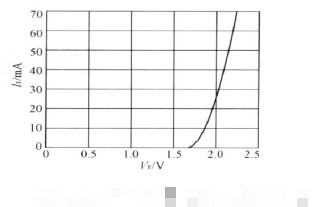
The figure below shows the relationship between forward voltage drop (VF) and forward current (IF). It can be seen from the curve that when the forward voltage exceeds a certain threshold (about 2V), that is, the so-called turn-on voltage, it can be approximately considered that IF is proportional to VF. The following table shows the electrical characteristics of the current major ultra-bright LEDs. It can be seen from the table that the highest IF of the current ultra-bright LED can reach 1A, while the VF is usually 2 to 4V.
The relationship between VF and IF of LED
In addition, the forward voltage drop of LEDs has a relatively large variation range (up to 1V or more). As can be seen from the VF-IF curve in the above figure, a small change in VF will cause a large IF change, resulting in a large change in brightness. Therefore, the use of constant voltage source driving cannot guarantee the consistency of LED brightness, and affects the reliability, life and light decay of LEDs. Therefore, ultra-bright LEDs are usually driven by a constant current source.
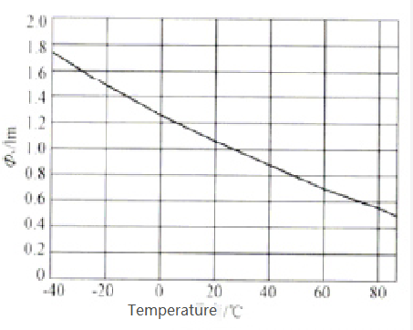
The figure below shows the relationship between the temperature and the luminous flux (φV) of the LED. It can be seen from the figure below that the luminous flux is inversely proportional to the temperature. The luminous flux at 85°C is half of that at 25°C, and the light output at 40°C is 1.8 times that at 25°C. The change of temperature also has a certain influence on the wavelength of LFD. Therefore, good heat dissipation is the guarantee that the LED maintains a constant brightness.
The figure below shows the relationship between the temperature and the luminous flux of the LED.
General LED Driver Circuit Introduction
Due to the constraints of LED power levels, multiple LEDs are often driven simultaneously to meet brightness requirements. Therefore, a special drive circuit is required to light the LED. The following briefly introduces the LED conceptual driving circuit.
Blocking current limiting circuit
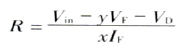
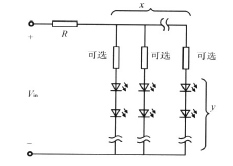
As shown in the figure below, the resistor current-limiting drive circuit is the simplest drive circuit, and the current-limiting resistor is calculated as follows.
where:
Vin is the input voltage of the circuit, Vin is the forward current of the LED, VF is the voltage drop of the LED when the forward current is IF, VD is the voltage drop of the anti-reverse diode (optional), y is the number of LEDs in each string, x is the number of strings of parallel LEDs.
The linearized mathematical model of the LED obtained from the above figure is:
where:
Vo is the turn-on voltage drop of a single LED, and Rs is the linearized equivalent series resistance of a single LED.
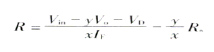
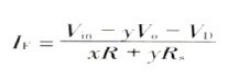
Then the calculation of the current limiting resistor in the above formula can be written as:
When the resistor is selected, the relationship between IF and VF of the resistor current limiting circuit is:
It can be seen from the above formula that the resistance current limiting circuit is simple. However, as the input voltage fluctuates, so does the current through the LED. Therefore, the regulation performance is poor. In addition, since the power lost by the connection of the resistor R is xRIF, the efficiency is low.
Introduction to Linear Regulators
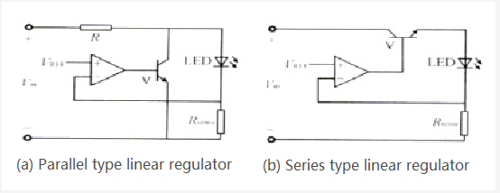
The core of the linear regulator is to use the power transistor or MOSFET working in the linear region as a dynamically adjustable resistor to control the load. Linear regulators are available in parallel and series.
Figure a below shows a parallel linear regulator, also known as a shunt regulator (only one LED is drawn in the figure, in fact, the load can be multiple LEDs in series, the same below), which is connected in parallel with the LED. As the input voltage increases or the LED decreases, the current through the shunt regulator will increase, which will increase the voltage drop across the current limiting resistor to keep the current through the LED constant.
Since the shunt regulator requires a resistor in series, it is not very efficient. And it is difficult to achieve constant regulation when the input voltage varies in a wide range.
Figure b below shows a series regulator. When the input voltage increases, the regulating dynamic resistance increases to keep the voltage (current) on the LED constant.
Power transistors or MOSFETs have a saturated on-voltage, therefore, the minimum input voltage must be greater than the sum of the saturation voltage and the load voltage for the circuit to work correctly.
Introduction to Switching Regulators
The above-mentioned driving techniques are not only limited by the input voltage range, but also have low efficiency. When used for low-power ordinary LED driving, the loss is not noticeable because the current is only a few mA. When used as a driver for a high-brightness LED with a current of several hundred mA or even higher, the loss of the power circuit becomes a serious problem.
The switching power supply is currently the most efficient in energy conversion, which can reach more than 90%. Power converters such as Buek, Boost, and Buck-Boost can all be used to drive LEDs, but in order to meet the constant current drive of LEDs, the feedback control is performed by detecting the output current rather than detecting the output voltage.
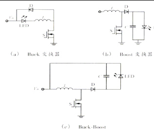
Buck converter
Figure (a) below shows the LED driver circuit using Buck converter. Different from the traditional Buek converter, the switch S is moved behind the inductor L, so that the source of S is grounded, which facilitates the driving of S. The LED is in series with L, and the freewheeling diode D is in anti-parallel with this series circuit. The driving circuit is not only simple, but also does not need an output filter capacitor, thereby reducing the cost. However, Buck converters are step-down converters and are not suitable for applications with low input voltage or multiple LEDs in series.
Boost Converter
Figure (b) above is an LED drive circuit using a Boost converter. Driving the LEDs at low input voltages is achieved by pumping the output voltage to a higher desired value than the input voltage through inductive energy storage. The advantage is that the output of such a driver IC can be used in parallel, effectively improving the power of a single LED.
Buck-Boost Converter
Figure (c) above is the LED drive circuit using Buck-Boost converter. Similar to the Buek circuit, the source of S in this circuit can be directly grounded, which facilitates the driving of S. Although the Boost and Buck-Boosl converters have one more capacitor than the Buck converters, they can both increase the absolute value of the output voltage. Therefore, it is used more when the input voltage is low and multiple LEDs need to be driven.