Power factor is never an issue. In the past, countries all over the world had regulations, requiring power exceeding 75 watts to have a power factor requirement. Therefore, there has never been any power factor requirement for lamps. Just like fluorescent lamps, the power factor is very poor, and no one has ever raised an opinion.
Later, there were energy-saving lamps, although the state put forward a requirement, but it was very loose, and there were only requirements for more than 15 watts. Most of the energy-saving lamps are less than 15 watts, so there is no requirement.
Only after the emergence of LED lamps, strict requirements have been raised. It is not required only under 5W, and power factor > 0.7 must be required for above 5W. Except for the small MR16 spotlights that are 3 watts, most LED lamps are more than 5 watts. So this regulation just got stuck on the neck of the LED. So, let’s take a closer look at the issue of power factor.
1. What is Power Factor
The relationship between voltage and current
We know that all generators are rotating machines and the voltage they produce is a sine wave, which is what we call alternating current.
One of the advantages of alternating current is that the voltage can be changed by a transformer through electromagnetic induction, and it can be raised to hundreds of thousands of volts for long-distance transmission to reduce transmission losses. After arriving at the destination, it will be lowered to become our commonly used mains power. Our current mains power is 220V~50Hz (or 110V~60Hz) alternating current.
In electrical engineering, alternating current can be represented by a vector. Vectors can represent voltages as well as currents. For a purely resistive load, the voltage and current are in phase. For purely capacitive or purely inductive loads, the current and voltage are not in phase, but have a 90-degree phase angle, or phase difference. With a purely inductive load, the voltage across it is 90 degrees ahead of the current. With a purely capacitive load, the voltage across it lags the current by 90 degrees.
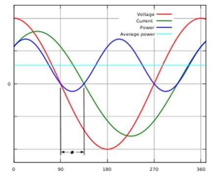
If we use waveform representation, we usually represent the voltage as a cosine wave. If the current lags the voltage, it is an inductive load, and if it leads the voltage, it is a capacitive load.
Figure 1. Relationship between AC Voltage and AC Current for Inductive Loads
Because in fact neither pure inductance nor pure capacitance exists, the actual load can only be called inductive load or capacitive load. At this time, there is an angle φ between the AC voltage and the AC current. For inductive loads, we call this angle φL. And for the included angle of capacitive load, it is called φC.
Definition of power factor
Power is equal to the product of voltage and current, but only when the load is purely resistive (voltage and current are in phase). In the case of an inductive or capacitive load, the current vector is projected onto the voltage vector (horizontal axis), that is, multiplied by cosφL or cosφC. We usually call this cosφL or cosφC the power factor.
However, since this angle can be positive or negative, the power factor may also be positive (inductive load) or negative (capacitive load).
When we use vectors to represent voltage and current, the premise is that their frequencies must be exactly the same. And it’s in a linear system.
In linear systems, we also express power factor as the ratio of active power to apparent power. The so-called active power is the product of the rms value of the voltage and the current in the same phase as the current. The apparent power is the “power” obtained by directly multiplying the effective values of the voltage and current without considering the phase difference between them. And the ratio of the two is obviously the cosine cosφ of the phase angle mentioned earlier.
2. Power Factor of Various Household Appliances
The power consumption and power factor of various household appliances, the results are as follows:
Name
Equipment capacity (W)
Power factor
Reactive power (var)
Apparent power (VA)
Lighting
200
0.90
96.86
222.22
Air conditioner
3000
0.80
2250.00
3750.00
Refrigerator
150
0.60
200.00
250.00
Microwave oven
1000
0.90
484.32
1111.11
Electric water heater
2000
1.00
0.00
2000.00
Rice cooker
1000
1.00
0.00
1000.00
Computer
300
0.80
225.00
375.00
Printer
250
0.80
187.50
312.50
TV
200
0.80
150.00
250.00
Washing machine
200
0.60
266.67
333.33
Range hood
50
0. 80
37.50
62.50
Audio
300
0.60
400.00
500.00
Water dispenser
600
1.00
0.00
600.00
Sanitary equipment
1000
1.00
0.00
1000.00
Health care equipment
600
0.80
450.00
750.00
Video recorder
200
0.90
96.86
222.22
DVD\VCD
100
0.90
48.43
111.11
Of course, these data are for reference only.
It should be noted:
(1). The power factor of all electric heating appliances is equal to 1, because they are all resistive loads.
(2). All household appliances with motors (most white goods) are inductive loads.
(3). All household appliances (TVs, stereos) with transformers are also inductive loads.
(4). A refrigerator that works continuously for 24 hours is an inductive load that consumes a lot of power and has a low power factor.
(5). Because the lighting fixtures are mainly incandescent lamps, the power factor will be close to 1.
3. Power Factor of Various Lamps
We know that the incandescent lamp has a power factor equal to 1 of course because it is a pure resistance. But the use of more and more fluorescent lamps and energy-saving lamps recently promoted by the country is not the case. For a long time, fluorescent lamps were started with a large inductor and a starter. After lighting, the large inductance is connected in series in the circuit, so it is basically an inductive load, and its power factor is only 0.51-0.56. After switching to electronic ballasts, the power factor is better. However, because electronic ballasts are easy to burn, the most used are still inductive ballasts. The power factor of energy-saving lamps is only about 0.54, and it is also an inductive load.
4. Power Factor of LED Lamps
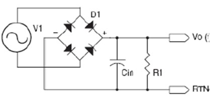
Figure 2. Equivalent circuit of an LED luminaire
Because LED is a semiconductor diode, it needs DC power supply. If powered by mains, there must be a rectifier, usually a diode rectifier bridge. To get the smoothest possible DC and avoid ripple and flicker, it is usually necessary to add a large electrolytic capacitor. The LED behind can be approximated as a resistor, so the whole circuit is shown in Figure 2.
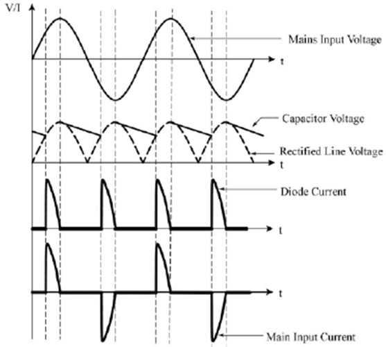
Its various currents and voltages are shown in Figure 3.
Figure 3. Voltage and current waveforms after bridge rectification and capacitor filtering
The voltage and current waveforms after rectification are not sine waves, and although the voltage waveforms before rectification are sine waves, their current waveforms are not sine waves either. So the whole system is a nonlinear system. Originally, the power factor is defined for a linear system, and the input and output voltages and currents are required to be sinusoidal at the same frequency, otherwise Cosφ cannot be used. However, in a non-sinusoidal system, because the voltage and current waveforms are not sinusoidal, there is no phase angle to say. Therefore, the power factor in nonlinear systems must be redefined.
As mentioned earlier, another definition of power factor is the ratio of active power to apparent power. Active power refers to the actual output power, while apparent power refers to the product of the rms value of the input voltage and the rms value of the input current. This is completely equivalent to Cosφ in a sine wave system, so there is no problem. But in nonlinear systems, what is active power and what is apparent power is worth discussing.
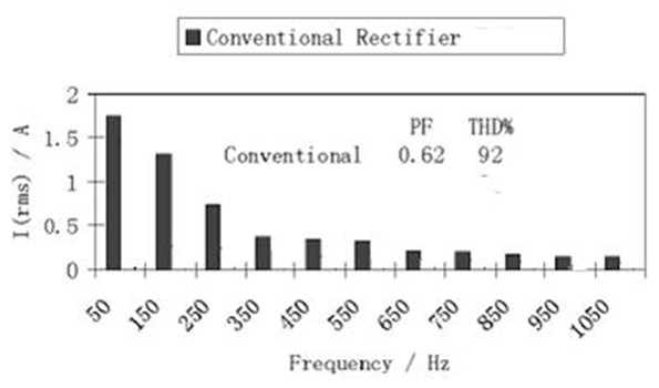
Figure 4. Current higher harmonics of a common bridge rectifier
Because in a nonlinear system, the current waveform has many high-order harmonics (see Figure 4).
What is apparent power
So what to take as its apparent power is a big problem. There are various approaches now.
(1). Algorithm #1
The apparent power is calculated by multiplying the fundamental rms value of the current and the sinusoidal voltage rms value. Or take the cosine of the fundamental current phase as the power factor. Or take the cosine of the zero-crossing phase of the current waveform as the power factor.
Some instruments measure this way. It can be seen from the waveform diagram of this current that the high-order harmonics of this waveform are very rich, and its fundamental wave is very small. If the fundamental wave current is used to multiply the fundamental wave voltage, then the power obtained is very small compared to the active power, so its power factor will be very high or even greater than 1.
This is the case, for example, in some analog power factor meters.
(2). Algorithm #2
The apparent power is calculated by multiplying the rms value of the voltage and the rms value of the current.
Many digital power factor meters now use the product of the RMS voltage and the RMS current as the apparent power.
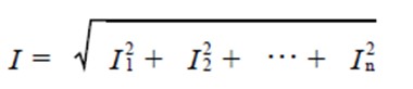
The effective value of non-sinusoidal current can be expressed by the root mean square value of each harmonic current:
If the power factor is defined to be equal to the ratio of actual power to apparent power
Many digital power factor meters today are basically defined in this way.
But the definition of power must be the product of voltage rms and current rms of a sine wave of the same frequency. The product of the rms value of the current higher harmonic and the rms value of the fundamental voltage cannot be regarded as power, because its frequencies are different, so it is a meaningless number. So using this method to define apparent power is problematic. Unfortunately, many digital meters now measure this way.
In fact, this issue has always been controversial in academia, so the American master’s thesis and the Swedish doctoral dissertation are still studying this issue.
In fact, in the case of nonlinear loads, the biggest problem is the harmonic current, because although the harmonic current cannot form apparent power with the fundamental voltage, the square of the harmonic current multiplied by the line resistance will cause heat loss. And this harmonic current cannot be compensated by simple capacitance or inductance. So, what really needs to be limited is the harmonic current value, not the so-called “power factor”.
5. Are the Current Regulations Reasonable?
Even if we accept the power factor value of LED lamps measured by the existing ordinary power factor measuring instrument, how much is allowed? According to the US Energy Star regulations, LED lamps with a power less than 5 watts do not require a power factor, while those greater than 5 watts require a power factor higher than 0.7. China now adopts the same rules as the US.
However, this provision is obviously unreasonable.
(1). Why is there a power factor requirement of 15 watts or more for mercury-containing “energy-saving lamps”, but more stringent requirements for LED lamps that are both energy-saving and environmentally friendly? The promotion is harmful and unhelpful.
(2). The power factor of most LED lamps is decimal, that is, capacitive load. The vast majority of home appliances are inductive loads. Originally, the Electricity Bureau needed to use large high-voltage capacitors to compensate on the secondary side of the transformer. Now, LED lamps can be compensated at the load end, which is obviously a good thing. Why limit it?
(3). Now many LED drive power supplies have added power factor correction to make it close to 1. But the irony is that the main reason why many LED driver chip companies developed high power factor chips was to be able to cooperate with thyristor dimmers (Triac), because the original thyristor dimmers only Can be used for pure blocking incandescent lamps with a power factor of 1.
Now LED lamps have improved power factor, so they can be matched with thyristor dimmers. However, after the thyristor dimmer is used, the overall power factor becomes worse and worse as the light is dimmed, and the overall efficiency is also getting lower and lower, completely losing the advantages of high efficiency and energy saving of LEDs .