The ideal power supply is inexpensive, 100% efficient, and takes up no space. Power electronics engineers are accustomed to hearing from customers, and they do their best to meet those requirements, trying to design systems within the smallest space and budget.
It is no exception when it comes to LED driver design, in fact it faces greater budgetary pressures. Because traditional lighting technology has been fully commercialized, its price has been very low. Therefore, it is very important to spend every penny under your budget. This is where some power electronics designers and engineers are ‘led astray’ by old habits.
Controlling the LED current to the same accuracy as the supply voltage to the digital load is a waste of electricity and money. 100mA to 1A is the current range for most products today, especially 350mA (or more precisely, 350mA/mm2 for opto-semiconductor junctions) is a commonly adopted compromise between thermal management and lighting efficiency.
The IC that controls the LED driver is silicon-based, so has a typical bandgap in the 1.25V range. To achieve 1% tolerance at 1.25V, a voltage range of ±12.5mV is required. This is not difficult to achieve, and there are many inexpensive voltage reference circuits or power control ICs that can achieve this tolerance or better.
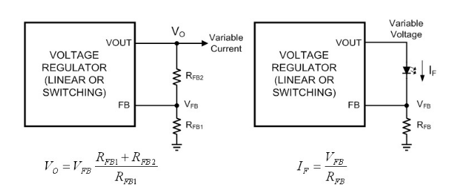
When controlling the output voltage, a high precision resistor can be used to feed back the output voltage at very low power (as shown in Figure 1a). To control the output current, some adjustments to the feedback method are required, as shown in Figure 1b. This is currently the only and easiest means of controlling the output current.
Figure 1a & 1b
How to deal with the defects brought by the low budget
A major disadvantage of doing this is that, after digging deeper, both the load and feedback circuits are identical. The reference voltage is applied across a resistor in series with the LED, which means that the higher the reference voltage or LED current, the more power the resistor will dissipate. Therefore, the reference voltage of the first-generation dedicated LED driver IC is much lower than that of current products. This is similar to a battery charger.
Lower voltage means lower power dissipation, which also means smaller, cheaper, lower loss current sense resistors. In the simple low-side feedback environment shown in Figure 1b, 200mV is the usual voltage choice. However, to achieve ±1% tolerance at a 200mV reference voltage requires a very expensive IC.
The tolerance relative to the nominal reference voltage is now ±2mV. While this is not impossible, higher accuracy comes at a higher cost. Tolerances of ±2mV require the production, testing, and grading techniques required for high-accuracy voltage references. At this point, the additional cost should be spent on smarter LED drivers. The value of the new expense is the addition of a feedback loop whereby the light output (instead of the current output) can be used to control how the LED is driven.
Measured Light Output
Just as digital product designers use simulation to solve problems when they encounter uncertain problems in power supply design, system architects who are power electronics engineers think of high-precision output when designing LED lamps.
LED manufacturers have clearly shown that the luminous flux is proportional to the forward current. Drive all LEDs with the same current, so each LED will produce the same luminous flux. Therefore, power electronics engineers come to the conclusion that high-precision current flow is necessary.
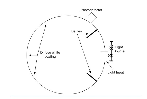
In doing so, they forget that lumens and lux (not amps) of light output are the point. Measuring current is easy, while measuring light requires expensive and large equipment. The integrating sphere shown in Figure 2, and most electronic engineers do not know much about integrating spheres.
Figure 2: Sectional view of the optical integrating sphere
Also, even though a current source with a tolerance of ±0.1% (which can be quite expensive) has a huge market value, it does little to produce a tight tolerance value in the actual light output. This can be determined by looking at the grading of LED luminous flux.
Calculated Light Output Accuracy
Knowing that LED light output from a single flux bin will have a tolerance of ±3% to ±10%, a system engineer might conclude that the drive current tolerance value must be as tight as possible.
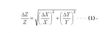
However, from a statistical point of view, this view is not correct. A common but incorrect assumption is that the overall tolerance of any value is equal to the simple sum of the worst-case values. The tolerance of the current source that powers the LED and the tolerance of the LED’s luminous flux are independent of each other – they are independent of each other from the very beginning. For two uncorrelated factors X and Y, the overall tolerance Z is not the sum of the tolerances of X and Y, but should be calculated using the following equation:
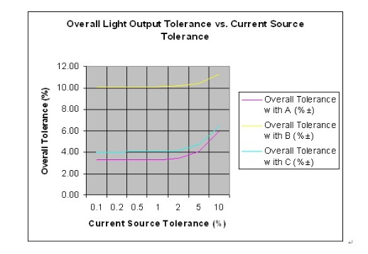
Figure 3: Light Output Overall Tolerance vs. Current Source Tolerance
According to Equation 1, it can be found that the effect of the lowest tolerance factor is greater than that of the others, and the actual overall tolerance value is much better than the sum of the worst-case tolerances of the individual factors, especially when one of the factors is much better than the other. Time. Looking at Figure 3, the most reasonable goal for the current source tolerance is to keep it within the tolerance of the LED light output. One thing to keep in mind: For cost reasons, many fixtures will use LEDs from different classes.
High Quality LED Lights Require More Feedback
LED manufacturers and their distribution partners are working hard to improve the luminous flux tolerance of their products, offering finer grading at a reasonable cost. For designers who want a product that lasts 5 years or 50,000 hours and maintains overall light output over the lifespan, even the densest flux grading and set 0.1% tolerance current The source is also difficult to achieve. Because the two important factors of heat and performance degradation over time can reduce the luminous flux of the LED, even the current source tolerance and the LED luminous flux tolerance of 0.001% will not solve the problem.
Given these losses, designers of high-quality solid-state lighting products must find power supplies with additional feedback loops, namely heat and light sources. To this end, dimming control is required, and an integrated circuit that can perform linear control and PWM (pulse width modulation) control on the output current becomes the best choice.
National Semiconductor’s LM3409 and LM3424 are LED driver control ICs, which are second-generation current sources for semiconductor lighting. Both products can control the average LED current value through a variable resistor or voltage source, and can provide a dedicated input signal for PMW (pulse width modulation) dimming signals.
In addition to the linear control loop, the analog regulation capabilities of the LM3409 and LM3424 also allow system designers to make their own choice between output current accuracy and trade-offs between size, cost and current sense resistor power dissipation.
Figure 4: LM3409/09HV Buck LED Driver
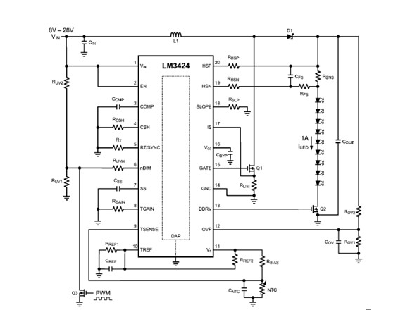
The LM3409/09HV control buck circuit shown in Figure 4 is the most commonly used circuit mode in power LED drivers. The LM3424 in Figure 5 can be used as a boost regulator LED driver, as well as a buck/boost, SEPIC (single-ended primary inductance converter), flyback, or even a “floating” buck circuit.
Application Areas Requiring Light Control
A street light is a good example of a light source because it has strict legal standards. For road lights, EU countries stipulate their minimum and maximum light output and lighting modes. For LED street lights that comply with this regulation and provide a lifetime of five years or more, the design must take into account the immediate luminous flux loss caused by heat and the flux loss caused by performance degradation over a longer period of time.
A natural approach is to use light sensors, such as photodiodes that form a linear control loop. On day one of the system, only a fraction of the overall available drive current should be used. This is done so that the drive current will slowly increase to an upper limit over time, thereby keeping the light output constant.
We can bias the photodiode and convert it into a PWM signal. This will help maintain a more constant relative color temperature over the dimming range with a simpler linear control loop. Generally speaking, the dimming range is also relatively small. PWM control is more useful when controlling light output based on different timing, motion sensors, or other power saving measures.
Summary
Output current accuracy is only one aspect of evaluating LED driver performance. But when the luminous flux tolerance of the LED itself is kept well above ±1%, it makes little sense even if the current source tolerance is as tight as the tolerance of the voltage rails in the digital processor. The average LED current tolerance should be approximately equal to the luminous flux tolerance.
This article illustrates an ideal situation based on a single level of error and gives some more practical examples. These examples use two or more binned LEDs, whose tolerances can also more easily be ±5%, ±10%, or more.
In the additional control loop, money should be used for 1% current control and power used for higher sense voltages. Some LED lights will emphasize simplicity and low cost, and even linear dimming will be too complicated and expensive. However, if you want to play the full performance of LED lamps, you need to use linear control or PWM (pulse width modulation control) or the coordinated use of the two to improve product performance and life.