At present, street lamps generally use the structure of high-pressure sodium lamps powered by mains. Among them, the electronic driving part of the high-pressure sodium lamp needs to convert the mains power from AC to DC, and then invert to AC to drive, resulting in low system efficiency. And because the utility power is used, complicated and expensive pipelines need to be laid.
Solar-LED street lights do not have the above problems. Since the output of the solar panel is DC power, and the LED is also a DC-driven light source, the combination of the two can improve the efficiency of the entire system. The use of solar energy also eliminates the cost of laying cables and related works.
With the increasing reduction of fossil energy sources and the excessive emission of greenhouse gases, the issue of global warming has been paid more and more attention. Environmental technology. As an inexhaustible clean energy, solar energy has become an important representative of many renewable energy sources.
In the field of lighting, LED solid-state lighting with long life, energy saving, safety, green environmental protection, rich colors and miniaturization has also been recognized as an important way of energy saving and environmental protection in the world. Solar-LED streetlights combine the best of both worlds, utilizing clean energy as well as high-efficiency LEDs for green lighting.
The solar-LED street light scheme introduced in this paper can automatically detect the ambient light to control the working state of the street light. Maximum Power Point Tracking (MPPT) guarantees maximum solar panel efficiency. Constant current control LED, with battery status output and user can set LED working time and other functions.
system structure
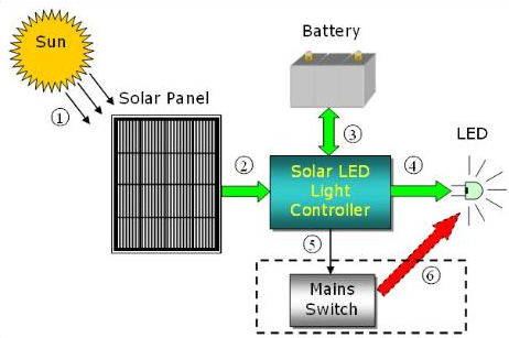
Figure 1 is a schematic diagram of the structure of a solar-LED street light. When the solar panel is irradiated by sunlight, the internal PN junction will form new electron-hole pairs, and a DC current can be generated in a loop. This current flows into the controller and somehow charges the battery. The battery is charged during the day and provides energy to the LEDs at night.
The work of the LED is carried out by the controller. While ensuring the constant current operation of the LED, the controller also monitors the status of the LED and controls the working time. In the case of continuous rainy days and insufficient battery power, the controller will send a control signal to start the external mains power supply system (not included in the controller) to ensure the normal operation of the LED.
The external mains power supply system is only used as a backup energy source and will only be used when the battery power is insufficient. The charging of the battery is done solely by solar energy to ensure maximum use of solar energy.
working principle
After the solar panel comes in, it will first be connected to the DC/DC converter (battery charging circuit) through a switch MOS tube KCHG. The output of this converter is connected to both ends of the battery (in the actual circuit, a fuse is first connected to the battery). In addition, KCHG has two functions: one is to prevent the reverse charging current from the battery when the output of the solar cell is low, and the other is to protect the circuit when the polarity of the solar panel is reversed.
The DC/DC converter uses a buck topology. The choice of topology must not only consider the maximum power point voltage of the solar panel and the maximum voltage of the battery, but also take into account the efficiency and cost.
A DC/DC converter (LED drive circuit) is also used between the battery and the LED to control the LED with constant current. Considering the fluctuation range of the battery voltage and the operating voltage range of the LED, a flyback topology is used in the design circuit to ensure constant current output. The efficiency of the flyback topology is generally not as high as that of a simple boost or buck circuit. If you want to improve the efficiency of the system, you can use a boost or buck circuit by optimizing the relationship between the battery voltage and the LED voltage to improve efficiency and possibly further reduce costs.
Controller
The role of the entire controller is achieved through a MCU. The main work of MCU includes the following points:
One is to use the MPPT algorithm to optimize the efficiency of solar panels.
The second is to use the appropriate charging mode for different states of the battery.
The third is to ensure the constant current output of the LED drive circuit.
The fourth is to judge day and night and use this to switch battery charging and discharging modes.
Finally, it provides functions such as monitoring protection, temperature monitoring, status output and user control input detection (DIP1~4).
The choice of MCU is mainly to meet the needs of ADC, GPIO and external interrupts, and does not need to simply pursue speed. Taking into account the needs of future expansion, the main control chip uses ST M32F101RXT6 (the latest ST M32 series MCU, using Cortex-M3 core).
The controller auxiliary power is converted directly from the battery. The battery input gets 12V through the linear power supply (L78L12), which supplies the logic circuit and PWM switching signal amplification. The 3.3V comes from the 12V switching power supply (L5970D), which mainly supplies power to the MCU and peripheral circuits.
The reason why switching power supply is used is to improve conversion efficiency (reduce battery power consumption) and provide sufficient load when the system is expanded in the future. Of course, in order to reduce the cost, it can be realized with a linear power supply.
The Main Function of the Controller
The main functions of the controller include two aspects: battery charging and battery powering the LED.
1. Battery charging
When the system detects that the ambient light is sufficient, the controller will enter charging mode. There are two important voltage values for battery charging: deep discharge voltage and float charging voltage. The former represents the state that the battery power is used up under normal use, while the latter represents the highest limit voltage for battery charging. These parameters should be found in the battery product manual.
In the design circuit, for the 12V battery, set the deep discharge voltage to 11V and the float charge voltage to 13.8V respectively (both are the voltage values at room temperature, and the corresponding temperature compensation is added to these two values in the software).
MPPT algorithm is used in trickle charging mode and constant current charging mode. There are many ways to implement the MPPT algorithm, and each has its own advantages and disadvantages. Relatively simple Perturbance and Observation are used in the design circuit to realize. The basic idea of this control method is to increase or decrease the duty cycle of the switching signal PWMCHG of the charging circuit, and then observe whether the output power increases or decreases, so as to decide whether to increase or decrease the duty cycle in the next step. Since the output of the solar panel changes relatively slowly and is a single pole, this method can still receive better results.
2. Battery discharge
When the system detects that the ambient light is insufficient, it will enter the battery-powered LED mode. The LED current is sampled by the high-level current detection chip (TSC101AILT) and sent back to the MCU, and the MCU obtains a constant output current by adjusting the duty cycle of the switching signal PWMDRV.
In order to achieve the purpose of energy saving, the constant current value of the LED will be adjusted according to the ambient light intensity detected by the system. When the ambient light changes from bright to dark, the output current of the system will correspondingly increase from small to large. When the ambient light is completely dimmed, the output current of the system also reaches the preset maximum value.
In addition to controlling the output of the LED by the ambient light, the user can also turn on the time control function by setting the state of the switches DIP1~4. The system will control the LED from 5 minutes to 12 hours according to the setting combination of DIP1~4.
In addition, in order to improve the reliability of the system, the design circuit adds a series of hardware and software protection functions for solar panels, batteries and LEDs. Based on this system platform, the system performance can be further optimized from three aspects: adding intelligent light-emitting diode working mode, adding communication module and adopting wind-solar hybrid system.
Conclusion
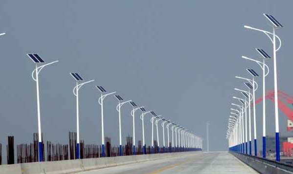
Solar-LED street lights can not only use clean solar energy and efficient and environmentally friendly LEDs to bring lighting to the road, but also reduce greenhouse gas emissions and achieve the purpose of green lighting. This street light system has been successfully implemented in many mountainous road sections, and all street light systems have been running for half a year and work normally. With the further reduction of the price of solar panels and the improvement of the cost-effectiveness of LEDs, it is believed that this system will be more and more widely used.