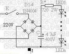
The resistance current-limiting small spotlight or table lamp using 220V AC power supply is characterized by its simple production. According to the level of the power supply voltage in the region, generally 90-100 tubes can be connected in series. If the number of tubes is too small, the efficiency is relatively low.
Adjust the current limiting resistor R appropriately according to the power supply voltage and the number of tubes to control the current of the LED, generally not more than 20mA. For areas where the power supply voltage is unstable and fluctuates greatly, the current of the LED will also fluctuate with the fluctuation of the voltage, which is its disadvantage.
The power of the current limiting resistor R requires more than 2W to avoid heat damage. The fewer the number of light-emitting tubes, the greater the resistance of R, and the greater the power.
The total power consumption of this circuit is less than 6W. If it is used to make spotlights, it is advisable to use condensing light-emitting tubes. If it is used to make general lighting table lamps, astigmatic light-emitting tubes should be used.
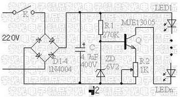
2. Constant Current Source Circuit
The 220V AC power source small spotlight or energy-saving lighting lamp using the constant current source circuit, although the circuit uses a few more components and increases the cost, but the use effect is much better than the circuit that only uses the resistance current limit. Even if the voltage fluctuates greatly, the circuit can still keep the current constant. This is very beneficial to the life of the light-emitting tube.
The main component transistor in this circuit requires a high-power transistor with a withstand voltage of more than 400V and a power of more than 10W, such as MJE13003, MJE13005, etc. And add heatsinks. The capacity of the filter capacitor C is 4.7uF, and the withstand voltage must be above 400V.
The size of the light-emitting tube current is determined by the adjustment of R2. For the convenience of adjustment, the variable resistor can be adjusted and then replaced with a fixed resistor of the same resistance value.
This circuit can bring as few as a dozen light-emitting tubes, up to more than 90. The current in this range can remain basically constant. The number of light-emitting tubes used in this circuit should not be too small, and the smaller the number, the lower the efficiency. The total power consumption of this circuit is about 6W.
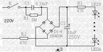
3. Capacitor Current-limiting eEergy-saving Lamps
The capacitor current-limiting energy-saving lighting lamp using 220V AC power supply has the advantages of low cost, small volume, and relatively constant current of the circuit. The magnitude of the current through the tube is mainly determined by C1.
This circuit has a perfect triple anti-impulse current design, which can protect the safety of the LED to the greatest extent. That is, R2 prevents the impact of the large current on the rectifier tube when the light is turned on. Capacitor C2 acts as a filter and works together with R2 and R3 to prevent the impact of large current on the light-emitting tube when the light is turned on. R3 also plays a role in preventing the high voltage and high current impact of the light-emitting tube by repeatedly switching the lamp in a short time.
When C1 is 0.33uF, the current of the circuit is within 20mA, which is most suitable for connecting less than 20 LEDs in series. The more the number of light-emitting tubes, the smaller the current. When there are more than 30 pieces, C1 can choose about 0.47uF, and the working voltage of C1 and C2 must be above 250V. The power of resistors R2 and R3 should be 1W.
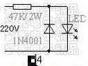
4. Resistive Step-down LED Lights
The resistance step-down night light or indicator using 220V AC power supply, as shown in the circuit diagram 4, has the advantages of the lowest cost and the smallest volume. But the efficiency is low, and a considerable amount of power is dissipated in the resistor. This circuit is most suitable for making a small current night light or indicator light and the like. The number of tubes is between 1 and 8 in series, which has little effect on the current of the circuit. The current of the circuit in Figure 4 is about 4mA, and it is more practical to use it as a night light with a total power consumption of less than 1W.
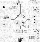
5. Telephone Lights Using Telephone Lines as Power Sources
The biggest advantage of using a telephone line as a power source is that there is no need to pay extra for electricity. Use it for as long as you want, especially as a night light. It is especially convenient for families with children and elderly people and people who need to get up at night.
The circuit of Figure 5 is the circuit used in general finished telephone lamps. In order to reduce the cost, the manufacturer adopts a relatively simple circuit, and in order to improve the brightness, the current is adjusted to a higher value. Therefore, some products cannot be used normally in some places after they are purchased.
When using this circuit to make your own, it should be noted that since the power supply voltage of each telephone line is not exactly the same, the current limiting resistor in the circuit needs to be adjusted according to the specific situation. In order to ensure that the incoming call is still ringing normally, and the phone will hang up automatically when the ring does not occur, the current can be increased as much as possible according to the local situation.
Generally, the current in the circuit is adjusted to about 2mA when the phone hangs up. Due to different situations in different places, in some places the current can be increased and the phone can still work normally. But if the current is too large, the light will be brighter, but it will affect the use of the phone.
The following provides the reference value of the resistance used in the series connection of different numbers of tubes when the current is about 2mA under the voltage of 48V. A pair of telephone lines can only be used for one telephone lamp at the same time.
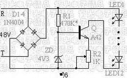
6. Telephone Lights with Current-expanding and Brightening Circuits
The circuit in Figure 6 is a very recently designed telephone light circuit that works very well. In this circuit, when the phone rings, the current will not rise as shown in Figure 5, but will also drop. Therefore, the current of the telephone lamp can be increased from 2 mA of FIG. 5 to at least 4 mA. This can not only greatly improve the brightness of the telephone lamp, but also better protect the safety of the light-emitting tube. When adjusting, you can also increase the current as much as possible according to the specific local conditions, while ensuring that the incoming call is still ringing normally, and the phone will not hang up automatically when the ringing occurs.
The maximum number of LEDs connected in series in this circuit is between 10-12 (due to the voltage drop of the LED and the voltage on the telephone line). The reduction of the number of LEDs will not affect the current of the circuit, and the magnitude of the current is adjusted by R2.
This circuit can also use 10-12 or less light-emitting tubes in series to form a group, and then use two or three groups to connect to the circuit in parallel. Although this connection method will reduce the current passing through each light-emitting tube, the total brightness will also be improved due to the increase in the total number of light-emitting tubes.
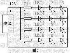
7. LED lights Powered by Power Converters
Lamps made by using power converters, mobile phone chargers and USB power supplies, etc., the circuit is shown in Figure 7. The advantage of lamps is safety and simplicity. The number and connection of the tubes used depend on the power supply voltage and output current.
Because the output voltage of these power supplies is relatively low and stable, resistors are generally used to limit current. The current limiting resistor is equal to the supply voltage minus (LED operating voltage multiplied by the number of LEDs) divided by the LED operating current.
The following provides a reference for the connection method under different power supply voltages when using a light-emitting tube with a normal working voltage of 3V and a current of 20mA. The power supply voltage should be based on the actual measurement. Because the internal resistance of each power supply is different and the normal working voltage of the LED is also different, the following values can only be used as a reference. In addition, if the power supply voltage is unstable, it is best to stabilize or stabilize the current before supplying power.
8. Lamps Powered by Ordinary Dry Batteries
Powered by ordinary dry batteries or rechargeable batteries and accumulators, it is safe and movable. No matter what kind of lamps are made, or used to modify automobile and motorcycle tail lights, turn signals, brake lights and interior lighting, refer to Article 7 according to the voltage of the battery.
The voltage difference between the old and new batteries or batteries before and after charging is relatively large, and it is best to regulate or stabilize the current.
The following introduces several kinds of lamp circuits powered by batteries:
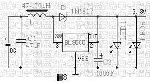
(1) Flashlight circuit using dedicated boost integrated circuit BL8505
Figure 8 is a flashlight circuit using a dedicated boost integrated circuit BL8505. When using a 1.5V battery, the output is 3.3V, and the current can reach 180mA, which can be used for 9 LEDs connected in parallel.
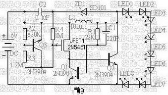
(2) LED series flashlight circuit using discrete components
If there is no dedicated boost integrated circuit, the circuit in Figure 9 can also be used to make a flashlight powered by four batteries. In order to ensure the consistency of the current flowing through each LED, the LEDs are connected in series. This requires a higher voltage to be applied to the light-emitting tube. Therefore, the boost circuit is composed of Q1 and Q2, and the control circuit is composed of Q3 and JFET1 field effect transistor. This circuit can raise the voltage of four batteries from 6V to more than 26V, which is enough to drive eight white LEDs connected in series.
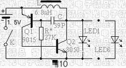
(3) LED parallel flashlight circuit using discrete components
The circuit in Figure 9 requires four batteries for power supply, so the resulting flashlight is inevitably bulky and the circuit is a little more complicated. The circuit of Figure 10 can be powered by only one battery, and the circuit is relatively simple. But LEDs can only be connected in parallel. This circuit can be connected in parallel with 8 white LED light-emitting diodes.
(4) Electric vehicle constant current lighting circuit using LM317 voltage regulator integrated circuit
Electric vehicles are powered by batteries, and their power consumption is relatively large, and their lighting is also very power-hungry. Therefore, the battery must be charged frequently, which will inevitably accelerate the aging and failure rate of the battery.
The use of LED light-emitting tube lighting with low power consumption can greatly reduce the consumption of the battery. Since electric vehicles are usually powered by 36V or 48V batteries, their maximum voltage can reach 42V or more than 56V. And as the load changes, the voltage is very unstable. Therefore, a constant current power supply must be used to ensure the stability of the light-emitting tube current.
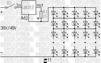
Figure 11 is the electric vehicle lighting circuit using the LM317 three-terminal adjustable voltage regulator integrated circuit to stabilize the current. The LM317 is connected in the form of a constant current source circuit. By adjusting the resistor R1, it can output 90mA current to supply power to the light-emitting tube.
The LEDs are of condensing type, and every 10 LEDs are connected in series as a group, and then 5 groups are connected in parallel. In order to maximize the efficiency of LEDs and ensure their safety, and to prevent the damage of one of the LEDs from affecting other LEDs, the LEDs are also connected in series and parallel LED arrays. In this way, the current flowing through each light-emitting tube is 18mA normally. When one of the LEDs is damaged, the current of the other four LEDs connected in parallel is only 22mA, which will not adversely affect the efficiency and life of the LED.