In order to realize the dynamic lighting design of the LED, the light color quantity of the light source needs to be controlled in real time to modulate the spectrum that meets the requirements of photobiology.
The amount of light color here is the collective name of luminosity and chromaticity. Commonly used dimming methods for LEDs include analog dimming and PWM (Pulse Width Modulation) dimming. The former is to linearly adjust the LED current, and the latter is to use a switching circuit to change the average value of the light output at a frequency that is sufficiently high relative to the recognition power of the human eye.
In the dimming process, it is very important to prevent the chromaticity from shifting. There are two main factors that cause color shift: forward conduction current and P-N junction temperature. The color difference produced by analog dimming depends on both. PWM is mainly determined by the latter.
In general, PWM produces small color difference (the color difference of white LED due to junction temperature does not exceed 4SDCM). In engineering practice, the chromatic aberration caused by PWM dimming is mostly ignored.
Characteristics of PWM Dimming
PWM under constant current drive has the following characteristics: changing the duty cycle of the LED, the luminosity changes linearly and the chromaticity remains constant. Luminosity and chromaticity are integer multiples of the average value of the square wave cycle time. PWM has also been widely used in engineering practice because of its wide adjustment range.
At present, there are relatively few studies on PWM dimming and color adjustment. Previously, there was a lack of a quantitative calculation scheme that used PWM to control the luminosity and chromaticity of the light source at the same time.
In response to the above problems, we proposed a two-channel PWM dimming and color mixing model, and established a one-to-one mapping between the desired light color and the duty cycle of the two channels. The algorithm can quantitatively modulate the spectra required by the desired luminosity and chromaticity. This provides an effective implementation method for LED dynamic lighting design.
Method
1 The certainty of two-channel PWM dimming and color adjustment
Theoretically, it can be proved that by mixing LEDs, there is a definite mapping relationship between the duty cycle of the two-channel PWM and the light color quantity of the mixed light. This certainty is jointly determined by the geometric, luminosity, and chromaticity constraints under the PWM mixing technology.
1.1 Geometric constraints
From the knowledge of chromaticity, the chromaticity coordinates of the mixed light must be on the line of the chromaticity coordinates of the two light sources participating in the mixing. The specific position depends on the mixing ratio of the two light sources. In this way, the geometric constraint conditions of the two-channel PWM light mixing are expressed by the formula as follows:
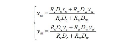
In the formula: xc, yc and xw, yw are the color coordinates of cold light source (high color temperature LED) and warm light source (low color temperature LED) participating in the light mixing under full current and duty cycle of 100%. xm and ym are the color coordinates of the mixed light.
1.2 Luminosity constraints
Changing the PWM duty cycle of driving the LED, the chromaticity does not change but the luminosity changes linearly accordingly, and the luminosity ratio is equal to the duty cycle ratio. According to the test conditions, the luminosity can be luminous flux, illuminance, brightness or light intensity. The chromaticity can be chromaticity coordinates or correlated color temperature.
If the duty cycle of the two light sources is known, the luminosity of the mixed light can be calculated as follows in combination with the principle of superposition:
In the formula, Yc and Yw are the luminosity of cold light source and warm light source participating in the light mixing under full current and duty cycle of 100%, respectively. Dc and Dw are the duty ratios of cold light sources and warm light sources, respectively. Ym is the luminosity of the mixed light. This is the luminosity constraint condition of the two-channel PWM light mixing.
1.3 Chromaticity constraints
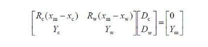
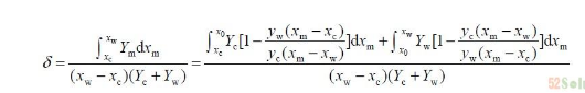
According to the principle of color mixing and CIE1931 color coordinate calculation method, when the duty ratios are Dc and Dw, the color coordinates of the two light sources after mixing should meet:
Where: Rc = Y c / yc, Rw = Yw / yw. In fact, it can be known from the geometric constraints that when the chromaticity coordinates of the two light sources and the x-coordinate of the mixed light are known, the y-coordinate of the mixed light is determined and unique. Therefore, the chromaticity constraint conditions of the two-channel PWM light mixing can be simplified as:
1.4 Quantitative calculation model of two-channel PWM dimming and color adjustment
Under PWM mixed light, the duty cycle is the only factor that controls the light color. If the desired luminosity is Ym and the desired color coordinate is (xm, ym), the duty cycle of the two channels can be obtained by combining the luminosity and chromaticity constraints.
If the desired chromaticity is a correlated color temperature, the desired correlated color temperature must be converted to the desired color coordinate in combination with geometric constraints. The conversion method is: make the Tm isotherm in the CIE1931 chromaticity diagram, and use the intersection of the line of (xc, yc) and (xw, yw) with this isotherm as the desired color coordinate (xm, ym). Combine formula (2) and formula (4) and write them as a matrix as follows:
From the knowledge of linear algebra, we know that when xc ≠ xw and yc ≠ yw, the system of equations has a unique solution. It can be seen that the duty cycle under a given desired chromaticity and luminosity value is determined and unique. At this time, the calculation of the duty cycle and the calculation of the light color quantity of the mixed light are reversible processes.
2. Limitations of two-channel PWM dimming
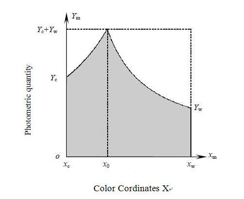
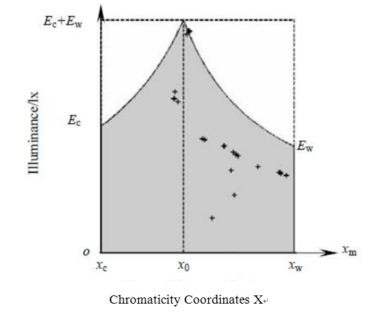
Theoretically, the value range of the mixed light color coordinate xm is [xc, xw] (set xc <x w), and the value range of the luminosity Ym of the mixed light is [0, Yc + Y w ]. The area enclosed by all possible values of mixed light chromaticity and luminosity is called the theoretical domain.
In fact, the two-channel PWM dimming and color adjustment method cannot realize all the values in the theoretical domain, but can only realize some specific areas. The achievable region is called the feasible region, and the boundary of the feasible region is mainly determined by the power constraints.
2.1 Electricity constraints
From a practical point of view, the duty cycle of the two channels should also satisfy 0 ≤ Dc ≤1, 0 ≤ Dw ≤1. Substituting the Dc and Dw obtained by formula (5) into the inequality, after simplification, the power constraint conditions under the two-channel PWM mixed light are obtained as follows:
The above-mentioned power constraints can be represented in Figure 1. In the figure, x0=(Rc xc + Rwxw )/(R c +Rw) is the color coordinate x of the mixed light when the duty ratio of the two LEDs is 1:1. The entire rectangular area shown in the figure is the theoretical area under two-channel PWM light mixing, and the shaded area is the feasible area. If the two LEDs participating in the light mixing have been selected, when using equation (5) to calculate the duty cycle to achieve the desired light color, first determine whether the desired value is within the feasible range. If it is in the feasible region, it can be obtained by the two-channel PWM light mixing method. Otherwise, consider replacing the light source that participates in the light mixing.
Figure 1: Theoretical and feasible regions of two-channel PWM dimming and color adjustment
2.2 Characterization of limitations
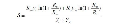
In order to characterize the ability of two-channel PWM dimming and color adjustment, the controllable ratio is defined, which is the ratio of the feasible domain to the theoretical domain. Expressed by the formula as:
In the formula: δ is the controllable ratio. After simplifying formula (7), we can get:
It can be seen from the above formula that the controllable ratio is determined by the two light sources involved in the light mixing, and has nothing to do with the external control method. The greater the controllable ratio, the greater the PWM control margin and the greater the probability of achieving the expected luminosity and chromaticity values. Therefore, the controllable ratio can be used as a criterion for judging the pros and cons of the combination of light sources.
It can also be seen from Figure 1:
1) The chromaticity of the mixed light can only take all the theoretical luminosity values at the position corresponding to x0,
2) If the luminosity of the mixed light is not greater than the smaller of Yc and Yw, all theoretical chromaticity values can be taken. So to achieve all chromaticity values, Yc and Yw should not be too different. And the smaller value of the two should be equivalent to the maximum value in the expected luminosity value.
The same experiment shows that the smaller the difference between Rc and Rw, the greater the controllable ratio, and the higher the utilization rate of the two LEDs. Therefore, when the expected value can be achieved, the light source combination with the smallest difference between Rc and Rw should be selected.
Experiment and Result Analysis
According to the change curve of daylight intensity and color temperature provided by the experiment, the light color values at 26 time joint points are selected to simulate the natural light from dawn to noon. According to the variation range of the light color value, two high color rendering white LEDs were selected.
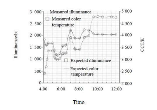
According to the limitations of the two-channel PWM dimming and color adjustment, the coordinate value of the expected light color value in the theoretical domain is calculated, as shown in Figure 2. Then calculate the duty cycle of each light color value falling in the feasible region according to formula (5). The single-chip microcomputer dynamically allocates the square wave with a specific duty cycle at each time point to the corresponding LED driver chip. The two LEDs are evenly distributed and the lights are mixed with opalescent glass, and the light color quantity of the mixed light is measured in real time with the detection equipment.
SUV3000 ultraviolet visible spectrum radiation analyzer is selected as the detection instrument. The measurement process is carried out in a standard dark room.
The average error between the measured illuminance value and the expected illuminance value is 15 lx, and the average error between the measured color temperature value and the expected color temperature value is 23K.
Causes of error
During the experiment, there is a certain error between the actual measured value and the theoretical value, but the overall match is still very good. The error mainly comes from the following aspects:
(1) As the experiment progresses, the junction temperature of the LED chip continues to rise. The change of junction temperature will cause the change of its light measurement and color measurement.
(2) The PWM waveform driving the LED chip is not an ideal square wave. Even in the same switching state, the current is not constant. The change of the driving current will cause the change of the luminosity and chromaticity of the LED. The smaller the duty cycle, the greater the error caused by this situation.
(3) LED individual differences. Even if it is the same model, the same batch of LEDs, the light and color metrics will be different, especially the dynamic characteristics of the two. In the experiment, it is believed that the same kind of LED has the same light, color, electrical parameters and dynamic characteristics.
(4) Detect the system error of the instrument and the random error in the operation process.
Figure 2 The distribution of experimental light color values in the theoretical domain.
Figure 3 simulates the change in illuminance and color temperature of natural light from dawn to noon.
Conclusion
This research proposes a new PWM-based dimming and color adjustment method, and establishes a one-to-one mapping model of the expected light color quantity and the two-channel duty cycle, which can accurately achieve the expected luminosity and chromaticity requirements of the spectrum. It provides a theoretical basis and implementation method for LED dynamic lighting technology. In addition, the dimming and color adjustment method also has potential application prospects in the field of LED backlighting.