It returns to the inside of the chip and is finally absorbed by the chip material or substrate through multiple internal reflections, and becomes heat in the form of lattice vibration, which makes the junction temperature rise.
The thermal dissipation ability of LED is another key factor to determine the junction temperature. When the heat dissipation capacity is strong, the junction temperature will decrease, on the contrary, when the heat dissipation capacity is poor, the junction temperature will increase. Because the epoxy adhesive is a low thermal conductivity material, the heat generated at the p-n junction is difficult to radiate upward to the environment through the transparent epoxy. Most of the heat passes through the substrate, silver paste, shell and epoxy adhesive layer, PCB and heat sink diverge downward.
The thermal conductivity of related materials will directly affect the heat loss efficiency of the components. For a common LED, the total thermal resistance from the p-n junction to the ambient temperature is between 300 and 300 For a power LED with good structure, the total thermal resistance is about 15 to 30 ℃ / W。 The large difference of thermal resistance indicates that ordinary LED can only work normally under the condition of very small input power, and the dissipation power of power LED can be as high as watt level or even higher.
What are the ways to reduce the junction temperature of LED?
Reduce the thermal resistance of LED itself,
Good secondary cooling mechanism,
Reduce the thermal resistance between LED and the mounting interface of the secondary cooling mechanism,
Control rated input power,
Reduce the ambient temperature
The input power of LED is the only source of the thermal effect of the components. Part of the energy becomes radiant light energy, and the rest of the energy eventually becomes heat, thus raising the temperature of the components. Obviously, the main way to reduce the temperature rise effect of LED is to try to improve the electro-optic conversion efficiency (also known as external quantum efficiency) of the device, so that as much input power as possible can be converted into light energy, and the other important way is to try to improve the thermal dissipation ability of the device, so that the heat generated by the junction temperature can be emitted to the surrounding environment through various ways.
LED product packaging steps
Production process
Production:
Cleaning: using ultrasonic cleaning PCB or LED product bracket, and drying.
Mounting: after silver glue is prepared on the bottom electrode of LED product die (large wafer), the expanded die (large wafer) is placed on the spinel stage. Under the microscope, the die is installed one by one on the corresponding pad of PCB or LED product bracket with a spinel pen, and then the silver glue is solidified by sintering.
Pressure welding: use aluminum wire or gold wire welder to connect the electrode to the chip of LED products, so as to be the lead of current injection. LED products directly installed on the PCB, generally using aluminum wire welding machine(Gold wire welding machine is needed to make white top-led products)
Package: protect the LED die and solder wire with epoxy resin through dispensing. When dispensing glue on PCB board, there are strict requirements on the colloid shape after curing, which is directly related to the brightness of backlight products. This process will also undertake the task of phosphor (white LED products).
Welding: if the backlight is smd-led products or other packaged LED products, the LED products need to be welded to the PCB board before the assembly process.
Cutting film: die cutting back light source with a punch required by a variety of diffusion film, reflective film, etc.
Assembly: according to the drawing requirements, the backlight materials will be manually installed in the correct position.
Test: check whether the photoelectric parameters and light uniformity of backlight are good.
Packing: the finished products are packed and put into storage according to the requirements.
Packaging technology
The task of LED product packaging
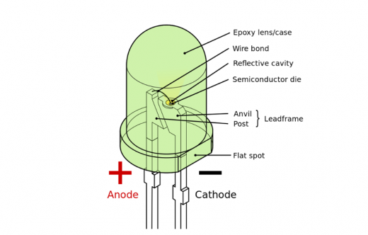
It is to connect the external lead to the electrode of the LED product chip, protect the LED product chip, and improve the efficiency of light extraction. The key processes are mounting, pressure welding and packaging.
Packaging form of LED products
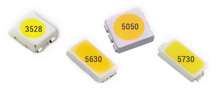
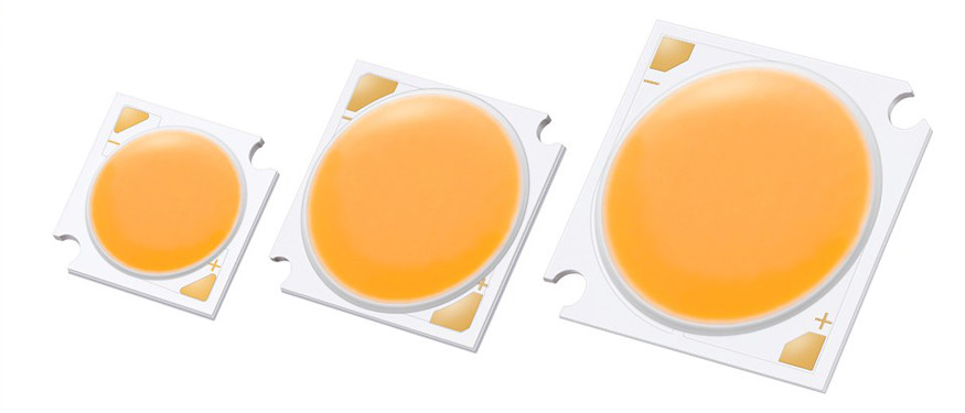
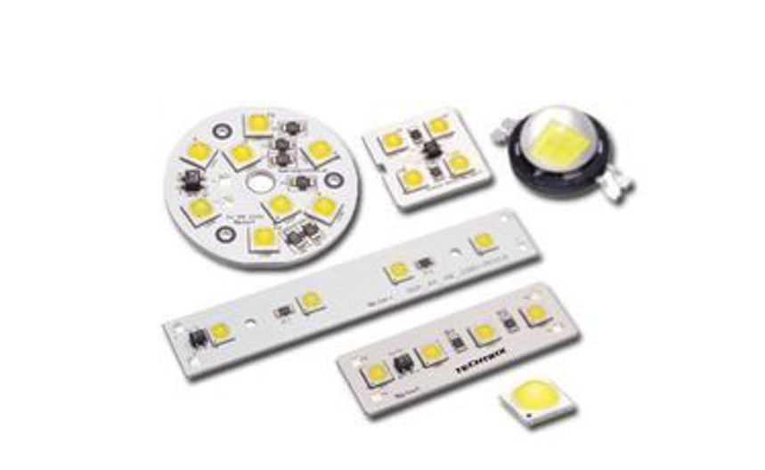
Product packaging can be said to be multifarious, mainly according to the different application of the corresponding dimensions, heat dissipation measures and lighting effect. LED products are classified into lamp LED products, top LED products, side LED products, SMD LED products, high power LED products and so on.
LED product packaging process
1. Chip test
Microscopic examination: whether there are mechanical damages and pockmarks on the material surface
Whether the chip size and electrode size meet the process requirements
Is the electrode pattern complete
2. Expansion
As the chips of LED products are still closely arranged after scribing, the spacing is very small (about 0.1 mm), which is not conducive to the operation of the later process. We use a chip expander to expand the film bonded to the chip, and the chip spacing of LED products is stretched to about 0.6 mm. Manual expansion can also be used, but it is easy to cause bad problems such as chip drop and waste.
3. Place silver glue or insulating glue on the corresponding position of LED product bracket( For the red, yellow and yellow green chips with back electrodes on GaAs and SiC conductive substrates, silver glue is used. For the blue and green LED product chips with sapphire insulating substrate, the insulating glue is used to fix the chips.)
The difficulty of the process lies in the control of the dispensing amount, and the detailed process requirements are given in the colloid height and dispensing position.
Due to the strict requirements for the storage and use of silver glue and insulating glue, the awakening, mixing and use time of silver glue must be paid attention to in the process.
4. Glue preparation
In contrast to dispensing, glue preparation is to apply silver glue on the back electrode of LED products by glue preparation machine, and then install the LED products with silver glue on the back bracket of LED products. The efficiency of glue preparation is much higher than dispensing, but not all products are suitable for glue preparation process.
5. Manual stabbing
The expanded LED product chips (with or without glue) are placed on the fixture of the stabbing table, the LED product bracket is placed under the fixture, and the LED product chips are stabbed one by one to the corresponding positions under the microscope. Compared with automatic mounting, manual chip pricking has one advantage, which is convenient to replace different chips at any time. It is suitable for products that need to install a variety of chips.
6. Automatic loading
In fact, automatic mounting is a combination of gluing (dispensing) and chip installation. First, silver glue (insulating glue) is applied on the LED product bracket, and then the LED product chip is sucked up and moved by the vacuum nozzle, and then placed on the corresponding bracket position.
In the selection of suction nozzle, try to use bakelite suction nozzle to prevent damage to the surface of LED chip, especially the blue and green chips must use bakelite. Because the steel nozzle will scratch the current diffusion layer on the chip surface.