LED is a characteristic-sensitive semiconductor device and has negative temperature characteristics. Therefore, it needs to be stabilized and protected during the application process, resulting in the concept of driving. LED devices have almost harsh requirements for driving power. Unlike ordinary incandescent bulbs, LEDs can be directly connected to 220V AC mains.
Constant current drive of LED
The LED is driven by a low voltage of 2 to 3 volts. It is necessary to design a complex conversion circuit. The LED lights for different purposes must be equipped with different power adapters.
In the international market, foreign customers have very high requirements for the efficiency conversion, effective power, constant current accuracy, power supply life, and electromagnetic compatibility of the LED drive power supply. When designing a good power supply, these factors must be considered comprehensively, because the power supply is in the entire lamp. The role of is as important as the human heart.
When using LED as a display or other lighting equipment or backlight, it needs to be driven with constant current, the main reasons are:
Avoid driving current exceeding the maximum rating and affecting its reliability.
Obtain the expected brightness requirements and ensure the consistency of the brightness and chromaticity of each LED.
Features of LED driver
According to the power rules of the power grid and the characteristic requirements of the LED drive power supply, the following points should be considered when selecting and designing the LED drive power supply:
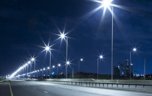
High reliability: It is especially like the driving power supply of LED street lights. It is difficult to maintain and costly to install at high altitude.
High efficiency: LED luminous efficiency decreases with increasing temperature, so heat dissipation is very important, especially
the power supply is installed in the lamp.
LED is an energy-saving product with high drive power efficiency, low power consumption, and low heat generation in the lamp, which helps reduce the temperature rise of the lamp and delay the light decay of the LED.
High power factor: Power factor is the requirement of the power grid on the load. Generally, there are no mandatory indicators
for electrical appliances below 70 watts. Although the power factor of a single electrical appliance with low power is low, it will have little impact on the power grid. However, if the lights are turned on at night, the similar loads are too concentrated, which will cause a serious load on the power grid. For LED driving power supplies of 30 watts to 40 watts, it is said that in the near future, there may be certain index requirements for power factor.
Constant current output power supply mode;
1) Multi-channel constant current output, flexible combination, one LED failure, does not affect the work of other LEDs, and the cost is slightly higher.
2) Direct constant current power supply, LED series or parallel operation. The cost is a bit lower, but the flexibility is poor. One LED fails and affects the operation of other LEDs.
These two forms coexist for a period of time. Multi-channel constant current output power supply mode will be better in terms of cost and performance. Maybe it is the mainstream direction in the future.
Surge protection: The ability of LEDs to resist surges is relatively poor, especially the ability to resist reverse voltage. It is also important to strengthen protection in this area. Some LED lights are installed outdoors, such as LED street lights. Due to the activation of the grid load and the induction of lightning strikes, various surges will be invaded from the grid system, and some surges will cause damage to the LED. Therefore, the LED drive power supply must have the ability to suppress the intrusion of surges and protect the LED from damage.
Protection function: In addition to the conventional protection function of the power supply, it is best to add negative feedback of LED temperature to the constant current output to prevent the LED temperature from becoming too high.
Protection aspect: The lamp is installed outside, the power supply structure should be waterproof and moisture-proof, and the outer shell should be light-resistant.
The life of the driving power supply should be matched with the life of the LED.
9. To meet the requirements of safety regulations and electromagnetic compatibility.
LED drive principle
The relationship curve between the forward voltage drop (VF) and the forward current (IF). From the curve, we can see that when the forward voltage exceeds a certain threshold (about 2V), which is commonly referred to as the turn-on voltage, it can be approximately considered that IF and VF is proportional. See the table for the electrical characteristics of current main super bright LEDs. It can be seen from the table that the highest IF of current ultra-bright LEDs can reach 1A, while VF is usually 2 to 4V.
Since the light characteristics of LEDs are usually described as a function of current, rather than a function of voltage, the relationship curve between luminous flux (φV) and IF, the use of constant current source drive can better control the brightness. In addition, the forward voltage drop of the LED has a relatively large range (up to 1V or more). From the VF-IF curve in the above figure, it can be seen that a small change in VF will cause a large change in IF, which will cause a greater brightness. Big change.
The relationship curve between LED temperature and luminous flux (φV). The figure below shows that luminous flux is inversely proportional to temperature. The luminous flux at 85°C is half of that at 25°C, and the light output at 40°C is 1.8 times that at 25°C. The temperature change also has a certain influence on the wavelength of the LED. Therefore, good heat dissipation is the guarantee for the LED to maintain a constant brightness.
Therefore, the use of constant voltage source drive cannot guarantee the consistency of LED brightness, and affects the reliability, life and light attenuation of the LED. Therefore, ultra-bright LEDs are usually driven by a constant current source.
LED drive circuit
Due to the limitation of the power level of the LEDs, it is usually necessary to drive multiple LEDs at the same time to meet the brightness requirements. Therefore, a special drive circuit is required to light the LEDs.
Resistance-capacitance step-down: Use the impedance of the capacitor under AC to limit the input current and obtain the DC
level to power the LED. The structure is simple, the cost is low, and the input is non-isolated, which has potential safety hazards.
The conversion efficiency is very low and constant current control cannot be achieved.
Isolated flyback circuit: Using a flyback circuit, a DC level is generated on the secondary side through a transformer, and then the ripple of this level is fed back to the primary side through an optocoupler, thereby self-excited and stable.
This kind of circuit meets the requirements of safety regulations, and the output constant current accuracy is better, and the conversion efficiency is higher. However, due to the need of optocoupler and secondary side constant current control circuit, the system is complicated, bulky, and costly.
Primary side solution: By completely controlling the output power and current on the AC primary side, the most accurate can achieve 5% constant current accuracy, and the secondary side only needs a simple output circuit.
The primary side mainly relies on the feedback of the auxiliary side to control the output voltage, relies on the current limiting resistor to control the primary side current, and at the same time multiplies the turns ratio to control the accuracy of the output current. The original-side solution inherits the advantages of the isolated flyback circuit, while the structure is simple, and it can achieve small size and low cost.
The problem of constant current accuracy of the primary side: The production accuracy of the transformation is difficult to control, resulting in a large output current drift when the primary side solution uses a low-quality transformer. Therefore, the primary-side solution is improved by adding a secondary-side constant current control circuit, which is more complicated than the ordinary primary-side solution, but compared with the flyback solution, the optocoupler can still be omitted, and the system has the highest cost performance.
LED drive method
Using a linear regulator to convert the voltage will face power consumption problems. This method is more suitable for use in conversion circuits that need to avoid noise (such as car audio) and cannot use the switch mode. The characteristic of the switching method is that the conversion efficiency is very high, but it also has the problem of noise, so the choice of the conversion method depends on the application.
Generally, the efficiency of the charge pump driving method changes with the change of the input voltage. In applications with a wide range of voltage changes, its efficiency is relatively low; and in applications with a relatively small range of voltage changes, only when the input and output voltages are different When the relationship is integral multiples, its efficiency can be maximized, but this is difficult to achieve in practical battery-powered applications. In contrast, the conversion efficiency of an inductor is not affected by voltage interference, and its application restrictions are less than that of a charge pump.
LED driver design ideas
The status of LED as a backlight source in portable products has been unshakable. Even in the backlight source of large-size LCDs,
LED has begun to challenge the mainstream status of CCFL (cold cathode fluorescent lamp); and in the field of lighting, LED is used
as a semiconductor The most critical components of lighting are sought after by the market because of the many auras of energy saving, environmental protection, long life, and maintenance-free. Drive circuit is an important part of LED (light emitting diode) products. Whether in the field of lighting, backlight or display panel, the choice of drive circuit technology architecture should match the specific application.
The light-emitting principle of LED is to add a forward voltage to both ends of it, so that the minority and majority carriers in the semiconductor will recombine, and the excess energy will be released, thus causing the emission of photons.
The main function of the LED drive circuit is to convert the AC voltage into a constant current power supply, and at the same time complete the matching of the voltage and current of the LED according to the requirements of the LED device.
Dimming method
Traditional dimming method; PWM (Pulse Width Modulation), using simple digital pulses to repeatedly switch the LED driver. The system only needs to provide wide and narrow digital pulses to easily change the output current to adjust the brightness of the LED.
Advantages; able to provide high-quality white light, simple application and high efficiency;
Fatal shortcomings; easy to produce electromagnetic interference, and sometimes even noise that human ears can hear.
The important task of LED drive circuit; boost
Inductance boost and charge pump boost are two different topological modes.
“Because the LED is driven by current, and the inductor has the highest efficiency during current conversion, the biggest advantage of the inductor boost method is its high efficiency, which can exceed 90% if properly designed;
The disadvantage is that electromagnetic interference is very strong, and the system requirements for communication products such as mobile phones are very high.
With the advent of charge pumps, the efficiency of boosting methods using charge pumps will be lower than that of inductive boosting.
The problem that product designers must face; improve the conversion efficiency of the drive circuit.
Conducive to extend the standby time of portable products, while solving the problem of LED heat dissipation, especially in the field of lighting using high-power LEDs
1) When the LED is working, it needs to have constant current and voltage-stabilizing components; it should have the characteristics of high voltage division and low power consumption, otherwise the higher efficiency LEDs will cause the overall system efficiency due to the high power consumption of the driving circuit. Greatly reduced.
2) As far as possible, do not use resistors or series voltage regulator circuits as the main current limiting circuit of the LED driver; instead, use high-efficiency circuits such as capacitors, inductors or active switching circuits to ensure the high efficiency of the LED system.
The use of series integrated constant power output circuit can keep the light output of the LED constant in a wide range of power supply, but the general IC circuit will therefore reduce the efficiency. The use of an active switch circuit can ensure that the constant power output is achieved when the power supply voltage changes greatly under high conversion efficiency.
But with its unique advantages, it can work efficiently under safe and special voltage (underwater lamps in swimming pools, paddling pools, miner’s lamps). In addition, it has its own unique advantages in the direct use of green electricity (solar energy, wind energy, etc.) and emergency lighting. Especially in terms of dimming, LEDs can not only achieve 0-100% dimming, but also ensure high light efficiency throughout the dimming process without compromising the life of the LED, which is difficult for gas discharge lamps.
DC control
LED is a device driven by current, and its brightness is proportional to the forward current. There are two ways to control the forward current.
The first method is to use the LED V-I curve to determine the voltage applied to the LED to produce the expected forward current. Its realization method generally adopts a voltage power supply and a ballast resistor. As described below, this method has several shortcomings. Any change in LED forward voltage will cause a change in LED current. If the rated forward voltage is 3.6V, the current of the LED is 20mA. If the voltage becomes 4.0V, which is a specific voltage change caused by temperature or manufacturing changes, the forward current is reduced to 14mA. An 11% change in forward voltage will result in a larger forward current change, up to 30%. In addition, depending on the available input voltage, the voltage drop and power consumption of the ballast resistor will waste power and reduce battery life.
The second method is also the preferred method of LED current adjustment is to use a constant current power supply to drive the LED.
high efficiency
Battery life is critical in portable applications. If the LED driver is practical, it must be highly efficient. The efficiency measurement
of an LED driver is different from that of a typical power supply. A typical power supply efficiency measurement is defined as output power divided by input power. For LED drivers, the output power is not a relevant parameter. What is important is the value of input power required to produce the expected LED brightness. This can be determined simply by dividing the LED power by the input power.
Please note: If the efficiency is defined in this way, the power dissipation in the current sense resistor will cause power dissipation
in the power supply. Through the formula shown in Figure 3, we can see that a smaller current sensing and voltage will produce a
higher efficiency LED driver. Figure 4 illustrates the efficiency improvement of the power supply with 0.25V reference voltage
compared with the power supply with 1V reference voltage. A lower current-sensing voltage power supply is more effective.
Regardless of the input voltage or LED current, as long as other conditions are the same, a lower reference voltage can improve
efficiency and extend battery life.
How long is the life of the LED driver
The working environment temperature of the capacitor in harsh environments will be greater than 95°C. Some people have also proposed whether ceramic or solid capacitors can be used, but the current capacitor technology cannot be made into high-voltage and large-capacity. Of course, a good saddle needs to be equipped with a good horse. The use of long-life capacitors does not necessarily guarantee the life of the power supply. To improve the life of the power supply, it needs to be improved in many ways: use a higher-life capacitor to improve the efficiency of the power supply and make a good power supply Optimized heat dissipation design of lamps and lanterns. In order to reduce the weight by considering the compact design of lamps, many lighting companies require the power supply to be made small and installed in a confined space, and the heat dissipation conditions of the power supply are limited. Therefore, high efficiency, small size and better heat dissipation design are the challenges faced by LED power supplies.
In traditional lamps, except for part of the power converted into light energy, most of the power is converted into infrared radiation energy and radiated to the outer space of the lamp, while LED lamps are different. LEDs emit light from semiconductors. Except for part of the power converted into light energy, most of the power is converted into heat energy, which can only be dissipated by the lamp body closely integrated with the chip.
For the overall beauty of the luminaire product structure, the merchants often design the LED power supply and the LED lamp body structure closely. The heat of the LED and the heat of the power supply are superimposed, so that the power supply and the LED light source are in a harsh working environment. When the temperature exceeds a certain temperature, the LED power supply and the life of the LED are greatly reduced. When the temperature protection is set inside the power supply, the lamp will be turned on and off repeatedly. If the temperature protection is not set, it will cause high temperature damage to the power supply device and accelerate the light decay of LED.
The LED power supply is a switching power supply. The quality and reliability of the switching power supply depend on its circuit design, production process, and quality of the device. Electrolytic capacitor is an essential part of high-power switching power supply.
The normal working life of the switching power supply depends on the life of the electrolytic capacitor used in the power supply, and the life of the electrolytic capacitor depends on the life of the capacitor itself and the operating temperature.
The working life of electrolytic capacitors varies greatly at different temperatures.
Take an outstanding foreign brand electrolytic capacitor as an example:
Its universal -40℃-+105℃ specification capacitor life guarantee value is 4000 hours (under 105℃ full load condition). If we use the maximum load value of capacitor ripple current to 85% when we design, then: according to the life estimation formula provided
The lifetime of the capacitor at 65℃ can only be guaranteed about 80,000 hours;
The lifetime of the capacitor at 75℃ can only be guaranteed for about 40,000 hours;
The lifetime of the capacitor at 85℃ can only guarantee about 20,000 hours;
The lifetime of the capacitor at 95℃ can only be guaranteed for about 10,000 hours;
Calculating from the above: every time the temperature of the electrolytic capacitor rises by 10°C, the lifetime will be halved.
Lamp working environment temperature: In some areas, the outdoor surface temperature can reach 40℃ or even higher in summer night.
The body temperature rise of the lamp: Since the large amount of heat generated by the LED itself relies on the shell to dissipate it, a reasonable design of the LED lamp shell temperature is between 20℃-25℃. That is: under the working condition of room temperature 25℃, the temperature of the lamp housing is about 45℃-50℃.
Self-temperature rise of the power supply: The temperature rise of the power device with a better power supply design is about 25-30℃, and the temperature rise of the poorer design is greater than 35℃. The outdoor LED power supply requires waterproof, and a sealed enclosure is required for the protection level. Increasing, manufacturers require glue processing. Different colloid materials have different prices and costs, and different thermal conductivity. Cheap glue has poor thermal conductivity and requires high-temperature baking, which will often cause different degrees of invisible damage and tight-bundle strains on components. , Leaving hidden dangers. (The poor heat dissipation treatment makes the working environment of the electrolytic capacitor in the shell like a thermos bottle, and the temperature accumulation cannot be released).