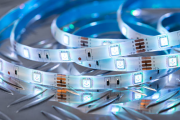
LED Product Packaging Process Introduction
Dispensing
Put silver glue or insulating glue on the corresponding position of LED bracket( For the red, yellow and yellow green chips with back electrodes on GaAs and SiC conductive substrates, silver glue is used. For blue and green LED chips with sapphire insulating substrate, insulating glue is used to fix the chips.)
Automatic mounting
In fact, automatic mounting is a combination of gluing (dispensing) and chip installation. First, silver glue (insulating glue) is applied on the LED bracket, and then the LED chip is sucked up and moved by the vacuum nozzle, and then placed on the corresponding bracket position.
In the process of automatic mounting, we should be familiar with the equipment operation programming, and adjust the gluing and installation accuracy of the equipment. In the selection of suction nozzle, try to use bakelite suction nozzle to prevent damage to the surface of LED chip, especially the blue and green chips must use bakelite. Because the steel nozzle will scratch the current diffusion layer on the chip surface.
Sinter
The purpose of sintering is to solidify the silver glue, and the sintering temperature should be monitored to prevent bad batch
The sintering temperature of silver glue is generally controlled at 150 ℃ and the sintering time is 2 hours. It can be adjusted to 170 ℃ for 1 hour according to the actual situation.
Insulation glue is generally 150 ℃ for 1 hour.
The silver glue sintering oven must be opened every 2 hours (or 1 hour) according to the process requirements to replace the sintered products, and the middle should not be opened at will. Sintering oven can not be used for other purposes to prevent pollution.
Pressure welding
The purpose of pressure welding is to lead the electrode to the LED chip to complete the connection of the internal and external leads of the product.
There are gold wire ball welding and aluminum wire pressure welding for LED. The picture on the right shows the process of aluminum wire pressure welding. First, press the first point on the LED chip electrode, then pull the aluminum wire over the corresponding bracket, press the second point, and then tear off the aluminum wire. In the process of gold wire ball welding, a ball is burned before pressing the first point, and the other processes are similar.
Pressure welding is a key link in LED packaging technology. The main process needs to monitor is the shape of the arch wire, the shape of the solder joint and the tension.
The in-depth study of pressure welding process involves many aspects, such as gold (aluminum) wire material, ultrasonic power, pressure of pressure welding, selection of cleaver (steel nozzle), movement track of cleaver (steel nozzle), etc. We’re not going to repeat it here.
Dispensing package
The packaging of LED mainly includes dispensing, potting and molding. Basically, the difficulties of process control are bubbles, lack of materials and black spots. In the design, the selection of materials, epoxy resin and bracket with good combination are the main points(Common LED cannot pass air tightness test).
Top LED and side LED are suitable for dispensing package. Manual dispensing packaging requires a high level of operation (especially white LED). The main difficulty is to control the amount of dispensing, because the epoxy will thicken during use. White LED dispensing also has the problem of color difference caused by phosphor precipitation.
Glued package
The encapsulation of lamp LED is in the form of encapsulation. The process of pouring is to inject liquid epoxy into the mold cavity of LED molding, then insert the press welded LED bracket, put it into the oven for epoxy curing, and then take the led out of the mold cavity.
Molded package
The press welded LED bracket is put into the mold, the upper and lower molds are closed with a hydraulic press and vacuumized, the solid epoxy is put into the entrance of the glue injection channel for heating, and the hydraulic ejector is used to press into the mold glue channel, and the epoxy enters into each LED forming groove along the glue channel and solidifies.
Curing and post curing
Curing refers to the curing of encapsulated epoxy. Generally, the curing condition of epoxy is 135 ℃ for 1 hour. The molding temperature is 150 ℃ for 4 minutes
Post curing is to allow the epoxy to fully cure, while the LED thermal aging. Post curing is very important to improve the bonding strength between epoxy and PCB. The general condition is 120 ℃ for 4 hours.
Slicing and dicing
As the LEDs are connected together (not individually) in the production, the lamp packaged led adopts rib cutting to cut off the rib of the LED bracket. Smd-led is on a PCB board, which needs dicing machine to complete the separation work.
Test
Test the photoelectric parameters of LED, check the dimensions, and sort the LED products according to the requirements of customers.
Packaging
Count and package the finished products, and the blue / White / Green super bright LED needs antistatic packaging.
The cause of LED junction temperature and the way to reduce it
What is the junction temperature of LED?
The basic structure of LED is a semiconductor p-n junction. The experiment shows that the temperature of p-n junction will rise when the current flows through the LED. Strictly speaking, the temperature of p-n junction is defined as the junction temperature of LED. Generally, because the chip has a very small size, we can also regard the temperature of LED chip as junction temperature.
What are the causes of LED junction temperature?
When LED works, the junction temperature can be increased in different degrees under the following five conditions:
- The poor electrode structure, the material of the window layer substrate or junction area and the conductive silver glue all have a certain resistance value. These resistances are added to each other to form the series resistance of LED components. When the current flows through the p-n junction, it will also flow through these resistors, resulting in Joule heat, resulting in the increase of chip temperature or junction temperature.
- Because the p-n junction can not be perfect, the injection efficiency of the device will not reach 100%, that is to say, in addition to the charge (hole) injected into the N region by the p region, the N region will also inject the charge into the p region ( In general, the latter kind of charge will not produce photoelectric effect, but will be consumed in the form of heating. Even if the useful part of the injected charge does not turn into light, some of it will combine with the impurities or defects in the junction region and eventually turn into heat.
- It has been proved that the limitation of light output efficiency is the main reason for the rise of LED junction temperature. At present, advanced material growth and component manufacturing technology have been able to convert most of the input electrical energy of led into optical radiation energy. However, due to the much larger refractive index of LED chip materials compared with the surrounding media, a large part of photons (> 90%) generated in the chip can not smoothly overflow the interface, resulting in total reflection between the chip and the media interface.
(To be Continued)

